Variable Frequency Transformer | Application:
So far we have considered transformers which operate at fixed frequency (50 Hz). Their purpose is to transform electric power from one voltage level to another; their performance measures being high efficiency and low voltage regulation. Small transformers (usually iron-cored) are used for coupling purposes in electronic circuits for communication, measurement and control. These Variable Frequency Transformer process signals which contain a wide band of frequencies (the width of band depends upon the signal measurement and control, audio, video, etc).
The two basic Application of variable frequency transformer are:
- Coupling of load to the source so as to maximize power delivered to the load. This application exploits the impedance transforming property of the transformer. Under condition of impedance matching the over-all efficiency of the system is as low as 50%. But in electronic circuit applications the performance criterion is the maximum power unlike the maximum efficiency in power system applications. Such transformers are known as output transformers while in audio applications these are known as audio-transformers.
- Providing a path for dc bias current through the primary while keeping it out of the secondary circuit.
An important requirement of these Variable Frequency Transformer is that the amplitude voltage gain (ratio of output/input voltage amplitude) should remain almost constant over the range of frequencies (bandwidth) of the signal. Further, it is desirable that the phase shift of output signal from the input signal over the signal bandwidth be small. We shall now investigate the gain and phase frequency characteristics of the transformer. This would of course include the effect of the output impedance (resistance) of the electronic circuit output stage. In these characteristics as the frequency range is quite large the frequency scale used is logarithmic.
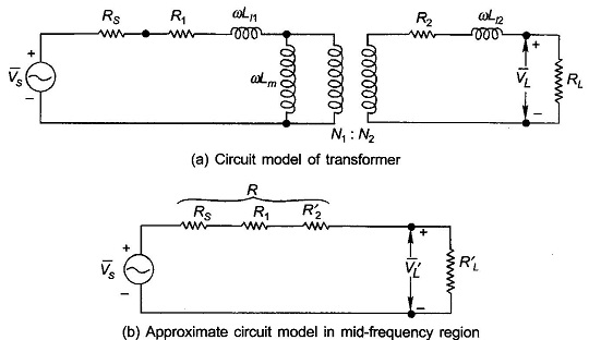
The circuit model of a Variable Frequency Transformer fed from a source of finite output resistance is drawn in Fig. 3.37(a) where the transformer core loss is ignored and leakage and magnetizing effects are shown in their frequency dependent form i.e., X = ωL. It may be observed here that Lm (megnetizing inductance) = L11 (self inductance of the primary coil).
Amplitude and phase response can be divided into three regions wherein the response calculations are simplified by making suitable approximations as below.
Mid–band region:
In this region the series leakage inductances can be ignored (as these cause negligible voltage drops) and the shunt inductance (magnetizing inductance) can be considered as open circuit. With these approximations the equivalent circuit as seen on the primary side is drawn in Fig. 3.37(b). It immediately follows from the circuit analysis that VL and VS are in phase, the circuit being resistive only. As for the amplitude gain, it is given as
![]()
High-frequency Region:
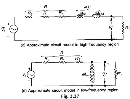
In this region the series inductances must be taken into account but the shunt inductance is an effective open circuit yielding the approximate equivalent circuit of Fig. 3.37(c). Amplitude and phase angle as function of frequency are derived below.
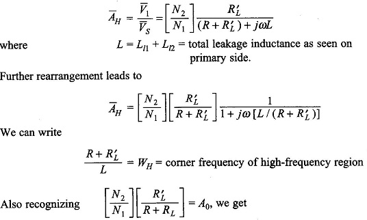
As per Eq. (3.80) the gain falls with frequency acquiring a valve of A0/√2 at ω/ωH=1 and a phase angle of ∠-45°. This indeed is the half power frequency (ωH).
Low-frequency Region:
In this region the series effect of leakage inductances is of no consequence but the low reactance (ωLm) shunting effect must be accounted for giving the approximate equivalent circuit of Fig 3.37(d). Amplitude and phase angle of frequency response is derived below.
The complete frequency ωL of this circuit is obtained by considering the voltage source as short circuit. This circuit is Lm in parallel with R||R′L.Thus![]()
The complex gain can be expressed as
![]()
Again the lower corner frequency is the half power frequency.
The complete amplitude and phase response of the transformer (with source) on log frequency scale are plotted in Fig. 3.38. At high frequencies the interturn and
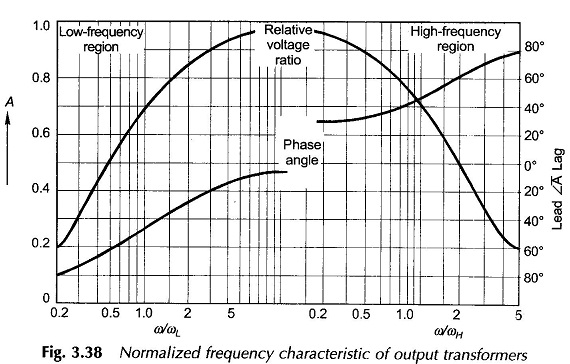
other stray capacitances of the transformer windings begin to play a role. In fact the capacitance-inductance combination causes parallel resonance effect on account of which an amplitude peak shows up in the high-frequency region of the frequency response. No reasonably accurate modelling of these effects is possible and best results are obtained experimentally. The frequency response of Fig. 3.38 gives a general guidance as to its nature.