Linear Variable Differential Transformer (LVDT):
The differential transformer is a passive inductive transformer. It is also known as a Linear Variable Differential Transformer (LVDT). The basic construction is as shown in Fig. 13.19.
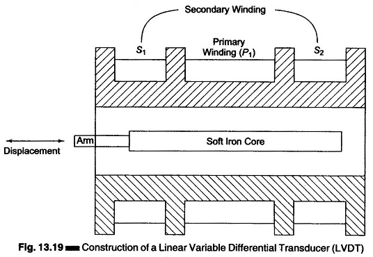
The transformer consists of a single primary winding P1 and two secondary windings S1 and S2 wound on a hollow cylindrical former. The secondary windings have an equal number of turns and are identically placed on either side of the primary windings. The primary winding is connected to an ac source.
An movable soft iron core slides within the hollow former and therefore affects the magnetic coupling between the primary and the two secondaries.
The displacement to be measured is applied to an arm attached to the soft iron core.
(In practice, the core is made up of a nickel-iron alloy which is slotted longitudinally to reduce eddy current losses.)
When the core is in its normal (null) position, equal voltages are induced in the two secondary windings. The frequency of the ac applied to the primary winding ranges from 50 Hz to 20 kHz.
The output voltage of the secondary windings S1 is Es1 and that of secondary winding S2 is Es2.
In order to convert the output from S1 to S2 into a single voltage signal, the two secondaries S1 and S2 are connected in series opposition, as shown in Fig. 13.20.
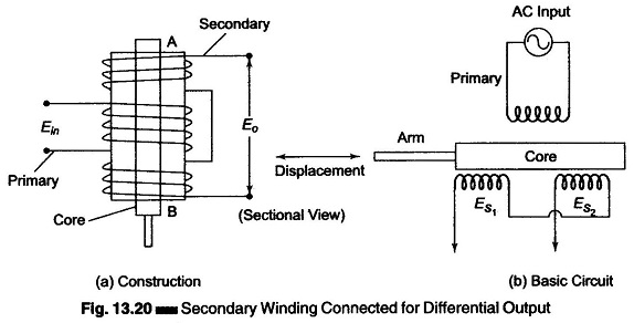
Hence the output voltage of the transducer is the difference of the two voltages. Therefore the differential output voltage Eo = Es1 ~ Es2.
When the core is at its normal position, the flux linking with both secondary windings is equal, and hence equal emfs are induced in them. Hence, at null position Es1 = Es2. Since the output voltage of the transducer is the difference of the two voltages, the output voltage Eo is zero at null position.
Now, if the core is moved to the left of the null position, more flux links with winding S1 and less with winding S2. Hence, output voltage Es1 of the secondary winding S1 is greater than Es2 . The magnitude of the output voltage of the secondary is then Es1 – Es2, in phase with Es1 (the output voltage of secondary winding S1).
Similarly, if the core is moved to the right of the null position, the flux linking with winding S2 becomes greater than that linked with winding S1. This results in Es2 becoming larger than Es1. The output voltage in this case is Eo = Es2 – Es1 and is in phase with Es2.
The amount of voltage change in either secondary winding is proportional to the amount of movement of the core. Hence, we have an indication of the amount of linear motion. By noting which output is increasing or decreasing, the direction of motion can be determined. The output ac voltage inverts as the core passes the centre position. The farther the core moves from the centre, the greater the difference in value between Es1 and Es2 and consequently the greater the value of Eo. Hence, the amplitude is function of the distance the core has moved, and the polarity or phase indicates the direction of motion, as shown in Fig. 13.21.
As the core is moved in one direction from the null position, the difference voltage, i.e. the difference of the two secondary voltages increases, while maintaining an in-phase relation with the voltage from the input source. In the other direction from the null position, the difference voltage increases but is 180° out of phase with the voltage from the source.
By comparing the magnitude and phase of the difference output voltage with that of the source, the amount and direction of the movement of the core and hence of the displacement may be determined.
The amount of output voltage may be measured to determine the displacement. The output signal may also be applied to a recorder or to a controller that can restore the moving system to its normal position.
The output voltage of an Linear Variable Differential Transformer is a linear function of the core displacement within a limited range of motion (say 5 mm from the null position).
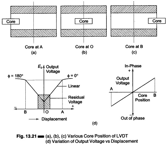
Figure 13.21(d) shows the variation of the output voltage against displacement for various position of the core. The curve is practically linear for small displacements (up to 5 mm). Beyond this range, the curve starts to deviate.
The diagram in Figs 13.21(a), (b) and (c) shows the core of an Linear Variable Differential Transformer at three different positions.
In Fig. 13.21(b), the core is at O, which is the central zero or null position. Therefore, Es1 = Es2, and Eo = 0.
When the core is moved to the left, as in Fig. 13.21(a) and is at A, Es1 is more than Es2 and Eo is positive. This movement represents a positive value and therefore the phase angle, is Φ = 0°.
When the core is moved to the right towards B, Es2 is greater than Es1 and hence Eo is negative. Therefore, S2 the output voltage is 180° out of phase with the voltage which is obtained when the core is moved to the left. The characteristics are linear from O – A and O – B, but after that they become non-linear.
One advantage of an Linear Variable Differential Transformer over, the inductive bridge type is that it produces higher output voltage for small changes in core position. Several commercial models that produce 50 mV/mm to 300 mV/mm are available. 300 mV/mm implies that a 1 mm displacement of the core produces a voltage output of 300 mV.
Linear Variable Differential Transformer are available with ranges as low as ± 0.05 in. to as high as ± 25 in. and are sensitive enough to be used to measure displacements of well below 0.001 in. They can be obtained for operation at temperatures as low as – 265°C and as high as + 600°C and are also available in radiation resistance designs for nuclear operations.
Advantages of LVDT:
- Linearity: The output voltage of this transducer is practically linear for displacements upto 5 mm (a linearity of 0.05% is available in commercial LVDTs).
- Infinite resolution: The change in output voltage is stepless. The effective resolution depends more on the test equipment than on the transducer.
- High output: It gives a high output (therefore there is frequently no need for intermediate amplification devices).
- High sensitivity: The transducer possesses a sensitivity as high as 40 V/mm.
- Ruggedness: These transducers can usually tolerate a high degree of vibration and shock.
- Less friction: There are no sliding contacts.
- Low hysteresis: This transducer has a low hysteresis, hence repeatability is excellent under all conditions.
- Low power consumption: Most LVDTs consume less than 1 W of power.
Disadvantages of LVDT:
- Large displacements are required for appreciable differential output.
- They are sensitive to stray magnetic fields (but shielding is possible).
- The receiving instrument must be selected to operate on ac signals, or a demodulator network must be used if a dc output is required.
- The dynamic response is limited mechanically by the mass of the core and electrically by the applied voltage.
- Temperature also affects the transducer.