Frequency Shift Keying Demodulator Working (FSK):
In digital data communication, binary data is transmitted by means of a carrier frequency. It uses two different carrier frequencies for logic 1 and logic 0 states of binary data signal. This type of data transmission is called Frequency Shift Keying (FSK). In this data transmission, on the receiving end, two carrier frequencies are converted into 1 and 0 to get the original binary data. This process is called as Frequency Shift Keying Demodulator.
A PLL can be used as a Frequency Shift Keying Demodulator, as shown in the Fig. 2.132.
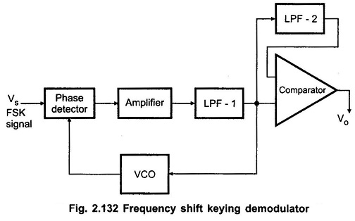
It is similar to the PLL demodulator for analog FM signals except for the addition of a comparator to produce a reconstructed digital output signal.
Let us consider that there are two frequencies, one frequency (f1) is represented as “0” and other frequency (f2) is represented as “1”. If the PLL remain is locked into the FSK signal at both f1 and f2; the VCO control voltage which is also supplied to the comparator will be given as
VC1 = (f1 – f0) / Kv and
VC2 = (f2 – f0) / Kv , respectively.
where
- Kv is the voltage to frequency transfer coefficient of the VCO.
The difference between the two control voltage levels will be
Δ VC = (f2 – f1) / Kv.
The reference voltage for the comparator is derived from the additional low pass filter and it is adjusted midway between VC1 and VC2.
Therefore, for VC1 and VC2, comparator gives output ‘0’ and ‘1’, respectively.