Tuned Collector Oscillator – Definition, Working and Equation:
The basic circuit of a tuned collector oscillator is shown in Fig. 21.7. It is called the tuned collector oscillator, because the tuned circuit is connected to the collector. The tuned circuit, constituted by the capacitor C and transformer primary coil L, forms the load impedance and determines the frequency of oscillation. The resistors R1, R2 and RE form the dc biasing circuit of the transistor. Capacitors C1 and CE are bypass capacitors for R2 and RE respectively so that the ac operation of the circuit is not affected. Moreover, C1 provides ac ground for the transformer secondary.
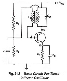
The output voltage developed across the tuned circuit is inductively coupled to the base circuit through transformer secondary coil L1. The feedback voltage appears across the base-emitter junction, as the junction point of resistors R1 and R2 is at ac ground due to by pass capacitor C1. The noteworthy point is that in the absence of C1, the feeding back voltage induced in the secondary of the trans¬former would not be directly going to the input of the transistor, some of this voltage will drop across resistor R2. A phase shift of 180° is provided by the transistor amplifier, as it is connected in CE configuration. Another phase shift of 180∘ is provided by the transformer. Thus a total phase shift of 360° appears between the input and output voltages i.e. there is a positive feedback between the input and output voltages. The transistor amplifier pro¬vides sufficient gain for oscillator action to take place.
Workings of Tuned Collector Oscillator:
When the supply VCC current is first switched on, a transient current is caused in the tuned L-C circuit. It is due to increase of collector current to its quiescent value. This transient current initiates natural oscillations in the tank circuit. These natural oscillations induce some voltage into L1 by mutual induction which causes corresponding variations in base current. These variations in base current are amplified β times and appear in the collector circuit.
A part of this amplified energy is used to meet the losses that occur in the tank circuit and the rest is radiated out in the form of electromagnetic waves. The turn ratio of L and L1 is determined by the total losses. Higher is the turn ratio, lesser is the feedback voltage applied and vice versa. The frequency of oscillation i.e. the frequency at which Barkhausen criterion is satisfied differs from the resonant frequency of the tuned circuit. This is due to loading of the transformer secondary to some extent.
Use of Natural Oscillations Set up in Tank Circuit:
The natural oscillations set up in the tank circuit are usually coupled to the next stage in the electronic system. There are various methods of coupling the output of the oscillator to the next stage. These include capacitive, transformer and impedance coupling networks. Usually, the output is taken from the tank circuit using inductive coupling, as shown in Fig. 21.8.
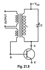
The output terminals are usually connected to the input terminals of the next stage—in rare cases to the power consuming device. This has the loading effect on the circuit causing increase in the circuit losses. For maintaining oscillations, more amount of positive feedback, which can be provided by simply increasing the coupling between the primary and secondary of the transformer, is required.
In case the load connected across the output terminals of the oscillator is too large, it may damp the oscillations. This is the reason that in a signal generator the output of the oscillator is connected through a buffer amplifier (emitter follower).
Frequency of Oscillation:
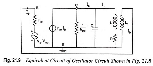
The equivalent circuit for the analysis of the Tuned Collector Oscillator is shown in Fig. 21.9. L-C tuned circuit constitutes the load,
The feedback fraction β, being the ratio of voltage induced in the secondary and voltage across the primary winding, is given as
![]()
The voltage gain of a CE amplifier without feedback is given as
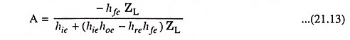
The negative signs in Eqs. (21.12) and (21.13) indicate that a phase shift of 180° is introduced by each of transformer and amplifier.
For Barkhausen criterion for sustained oscillations
![]()
Substituting the values of A and β from Eqs. (21.13) and (21.12), we have
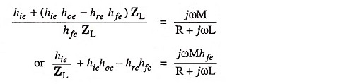
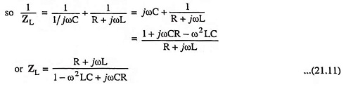
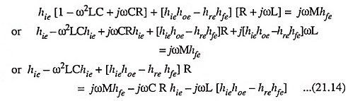
Substituting the value of ZL from Eq. (21.11), we have
Equating the real part of above Eq. (21.14) to zero, we have
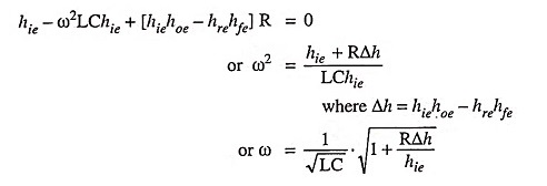
Thus, the frequency of oscillation is given as
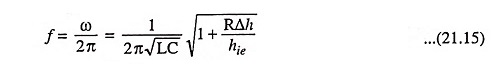
Since Δh and resistance R of the coil is very small and hie is large, therefore, the Eq. (21.15) can he written as
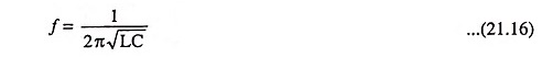
Thus the frequency of oscillation can be varied by varying either L or C. However, it is easier to vary C.
Condition for sustained oscillations can be obtained by equating the imaginary term to zero. Thus
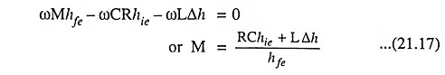
The above equation gives the minimum value of the mutual inductance M, which is required for sustained oscillations.