Emitter Follower at High Frequencies:
Emitter Follower at High Frequencies circuit is given in Fig. 19.48(a). A capacitance CL is included across the load because the emitter follower is often used to drive capacitive loads. This is because of its small output impedance.
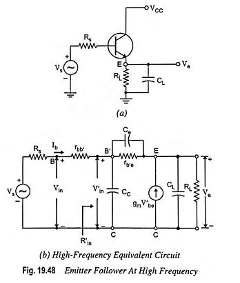
Applying Kirchhoff’s current law to nodes B′ and E respectively [Fig. 19.48(b)], we have
![]()
and
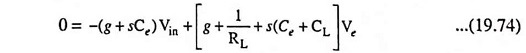
where
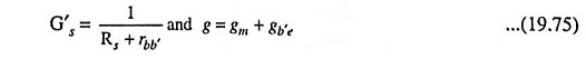
By elimination of V′in from above equations, the voltage gain Ve/Vs is obtained in terms of s.
A very simple approximate expression for the transfer function can be obtained by applying Miller’s theorem to the circuit given in Fig. 19.48 (b).
The low frequency gain of an emitter follower is approximately equal to unity i.e. K ≈ 1 and K – 1 ≈ 0. Thus input time constant τin ≈ (Rs + rbb′) Cc and the output time constant τout is proportional to CL. Since load is assumed to be highly capacitive, τout >> τin. It means that the upper 3-dB frequency is determined to a good approximation, by the output circuit alone. Using K = 1, we have
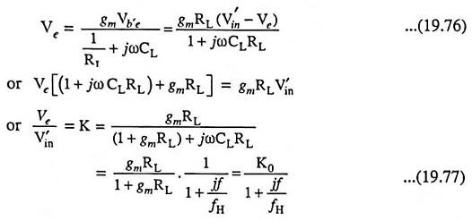
where

and
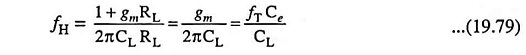
Since we know, fT = gm/2πCe, we see that τout = CL/gm and the condition τout >> τin needs
![]()
Since the input impedance between terminals B′ and C is very large in comparison to Rs + rbb′, then K represents the overall voltage gain
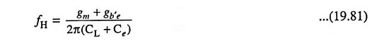
A somewhat better approximation for fH is given as
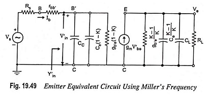
Input Admittance: Input admittance, excluding rbb′, can be determined by making reference to Fig. 19.49.
Substituting the value of K from Eq. (19.77) in above equation, we have
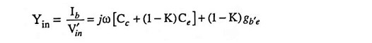
Input admittance,
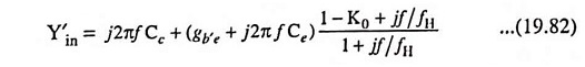
Since K0 is approximately equal to unity, the numerator of Eq. (19.82) is affected by frequency at a much lower value of f than is the denominator. Thus, for f < fH, Eq. (19.82) may be written as
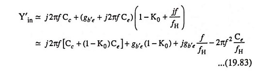
where the last term represents a negative resistance which is a function of frequency. Thus, the input impedance consists of a capacitance shunted by a negative resistance. If the source resistance have some inductance in series with it, it is possible for the circuit to sustain undesirable oscillations. This condition can be avoided if we use a small resistance in series with Rs so that the net resistance seen by the source is positive.