Voltage Follower Op Amp:
A circuit in which the output voltage follows the input voltage is called voltage follower circuit. The Voltage Follower Op Amp circuit diagram is shown in the Fig. 2.23.
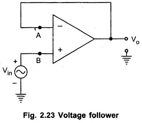
The node B is at potential Vin. Now node A is also at the same potential as B i.e. Vin.
![]()
Now node A is directly connected to the output. Hence we can write,
![]()
Equating the equations (1) and (2),
![]()
For this circuit, the voltage gain is unity.
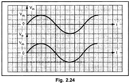
Thus the output voltage Vo is equal to the input voltage Vin. If Vin increases, Vo also increases. If Vin decreases, the Vo also decreases. Thus output follows the input hence the circuit is called voltage follower circuit. It is also called source follower, unity gain amplifier, buffer amplifier or isolation amplifier. The input and output waveforms Voltage Follower Op Amp circuit are shown in the Fig. 2.24.
Advantages of Voltage Follower Op Amp:
The advantages of such Voltage Follower circuit are,
- Very large input resistance, of the order of M Ω.
- Low output impedance, almost zero. Hence it can be used to connect high impedance source to a low impedance load, as a buffer.
- It has large bandwidth.
- The output follows the input exactly without a Phase shift.
Because the input resistance of the voltage follower is extremely large, it draws negligible current from the signal source. Therefore the signal source is not loaded. This property is most suitable in the instrumentation amplifier, which is used to amplify the signal output from a transducer.
If the output of a transducer is directly applied to the input of an amplifier which does not have high input impedance, then there is every possibility that the transducer may get loaded. Loading alters the characteristics of the transducer. To prevent this, the voltage follower circuit can be used in between the transducer and the amplifier. Such an use of the voltage follower is called an isolator or a buffer.