Bistable Multivibrator – Working and Types:
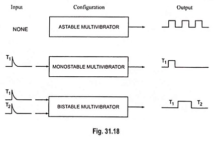
A bistable multivibrator, as its name implies, has two stable states. It can stay in either of the two states indefinitely (as long as dc power supply remains on). Only an application of a suitable trigger pulse makes the circuit to change to the other stable state. The circuit can be brought back to its original stable state only by applying another suitable trigger pulse. Thus one trigger pulse causes the multivibrator to flip from one state to another and the next pulse causes it to flop back to its original state. This is the very reason that it is called the flip-flop multivibrator. The bistable multivibrator is employed in many digital operations such as counting and storing of binary information, as a frequency divider in timing circuits and can also be used for generation of pulses.
Types of Bistable Multivibrator:
The bistable multivibrator circuits considered here are of two types viz. fixed-bias bistable and self-bias bistable multivibrators. Fixed-bias bistable multivibrator makes use of two separate sources for biasing the devices whereas self-bias multivibrator uses one self-bias to derive the biasing voltage.
Beside these two circuits, there is a third variation of bistable multivibrators, namely, the Schmitt trigger. This circuit, in addition to being used as a bistable, may also be employed for other applications like waveshaping, comparators etc.
Fixed Bias Bistable Multivibrator:
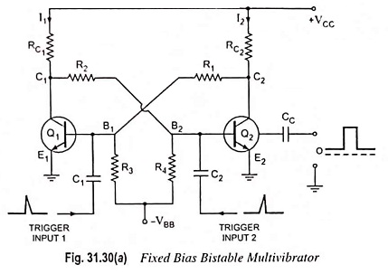
The circuit of a fixed bias bistable multivibrator is shown in Fig. 31.30 (a). It consists of two identical transistors Q1 and Q2 with equal collector resistors RC1 and RC2 and with output of one supplied to the other. The feedback is coupled through resistors R1 and R2. The output may be taken from either of the two transistors Q1 and Q2.
Working:
When power is first applied to the circuit, both transistors start conducting. Because of small differences in their operating characteristics, one of the transistors will conduct slightly more than the other. This starts a series of events. Assume arbitrarily that transistor Q1 initially conducts more than transistor Q2. This causes the collector voltage of transistor Q1 to drop more rapidly than that of transistor Q2. The resulting negative signal is fed to the base of transistor Q2. The falling voltage makes the conduction of Q2 less. Thus, its collector current starts falling with corresponding increase of voltage at terminal C2. This increasing voltage is applied to the base of transistor Q1 which makes it more forward biased. Because of this cumulative feedback within no time transistor Q1 goes to saturation and Q2 to cut-off. The output of saturated transistor Q1 is approximately zero and that of cut-off transistor Q2 approximately VCC. This is the first stable state of the multivibrator. The multivibrator can be driven from the first stable state (Q1 on and Q2 off) to the other stable state (Q1 off and Q2 on) by applying either a negative trigger pulse to the base of transistor Q1 or a positive trigger pulse to the base of transistor Q2.
Let a negative pulse of short duration and sufficient magnitude be applied to the base of transistor Q1 through capacitor C1. This reduces the forward bias on transistor Q1 and causes a reduction in collector current and, thereby, increase in potential of its collector terminal C1. The rising collector voltage appears across the emitter-base junction of transistor Q2 as it is connected to collector terminal C1 via resistor R2. As a result collector current of transistor Q2 increases and, therefore, its collector voltage falls. The decreasing collector voltage appears across the emitter-base junction of transistor Q1 where it further reverse biases the emitter-base junction of transistor Q1 to make collector current to fall. After few cycles, the transistor Q2 is driven into saturation and transistor Q1 to cut-off. This is the second stable state of the multivibrator. The circuit will now remain in this second stable state (Q1 off and Q2 on) until a positive pulse is applied to the base of transistor Q1 or a negative pulse to the base of transistor Q2.
The noteworthy points are :
1. Under cut-off condition nearly the full supply voltage VCC appears across the transistor and this restricts the supply voltage VCC to the order of several tens of volts (smaller than the transistor breakdown voltage VCE).
2. Under saturation condition, the collector current is maximum. Hence RC1 and RC2 must be chosen so as to restrict the collector current to the permissible value. The values of resistors R1, R2, R3 and R4 and VBB must be so selected that in one state the base current is large enough to drive the transistor into saturation while in second state the emitter-base junction must be below cut-off value.
3. The values of R1, R2, R3 and R4 are selected so that they are much larger than collector resistances RC1 and RC2 and consequently have no loading effects on the amplifier circuit.
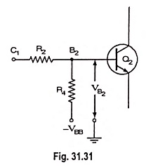
Analysis: If transistor Q1 is in conducting state and transistor Q2 is in non-conducting state, the voltages VB1 between point B1 and ground (points E1 and E2) and VC1 between point C1 and ground are both small. The base-bias voltage VB2 on transistor Q2 is then
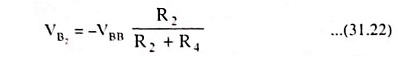
which being negative, keeps transistor Q2 in its cut-off state. Since RC2 is much smaller than R1 and the collector current of transistor Q2 is assumed zero, the collector voltage of transistor Q2 is + VCC. The base current IB1 is then
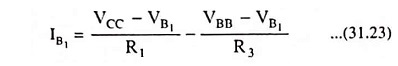
and if VB1 can be considered negligibly small,

For keeping transistor Q1 conducting, the value of IB1, must be sufficiently positive to ensure continued current i.e.,
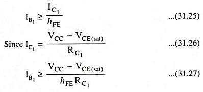
The values of VCC, VBB, R1, R2, RC1 and RC2 are so selected that Eq. (31.27) is satisfied and consequently a stable state exists with Q2 cut-off and Q1 in saturation. For the symmetry of circuit (RC1 = RC2; R1 = R2 and R3 = R4), it is evident that a second stable state exists with Q1 cut-off and Q2 in saturation.
Two points should be noted about the switching process. First the pulse used for switching need only be applied for a time sufficient for the changeover; it can then be removed. Second, if a negative pulse is used to affect switching, a positive pulse is required for the next switching, a negative pulse for the one following, etc.
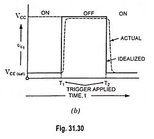
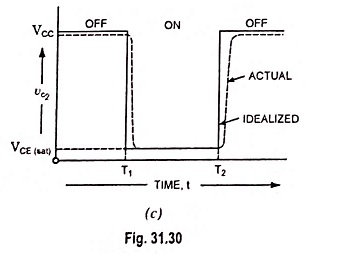
Idealized output waveforms for the bistable multivibrator are shown in Fig. 31.30 as solid curves. The dotted waveforms are those of an actual circuit, the deviations from the idealized result from switching transients.
Loading: The bistable multivibrator may be employed to drive other circuits and therefore at one or both the collectors there are shunting loads which are not indicated in Fig. 31.30(a). Such loads reduce the magnitude of the collector voltage VC1 of the cut-off transistor. This will cause reduction in the output voltage swing. A reduced VC1 will result in the reduction of IB, and it is possible that transistor Q2 may not be driven into saturation. Hence, the components of the multivibrator must be chosen so that under the heaviest load, which the multivibrator drives, one transistor remains in saturation while the other is in cut-off.
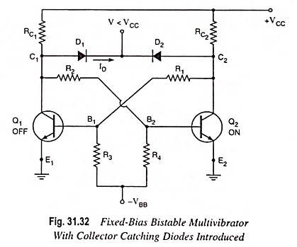
For some applications, the loading varies during the operation. In such cases, the extent to which a transistor is driven into saturation varies. A constant output swing Vw = V, and a constant base saturation current IB, can be had by clamping the collectors to an auxiliary voltage V < VCC through the diodes D1 and D2 as shown in Fig. 31.32. As transistor Q1 cuts off, its collector voltage increases and when it becomes V, the collector “catching diode” D1 conducts and clamps the output to V.
Self Bias Bistable Multivibrator:
The circuit of a self-biased bistable multivibrator is shown in Fig. 31.33.
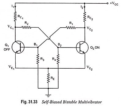
Here the emitter of both the transistors are common and a resistance RE is connected from the common emitter to ground. The voltage drop across RE provides the self-bias to keep one of the transistors in the off state. The two stable states of the bistable multivibrator (binary) are:
- Transistor Q1 off and transistor Q2 on.
- Transistor Q2 off and transistor Q1 on.
The working and operation of self-bias binary is the same as that of fixed-bias binary.