Monostable Multivibrator Using IC 555:
The IC 555 timer can be operated as a Monostable Multivibrator Using IC 555 by connecting an external resistor and a capacitor as shown in the Fig. 2.102.
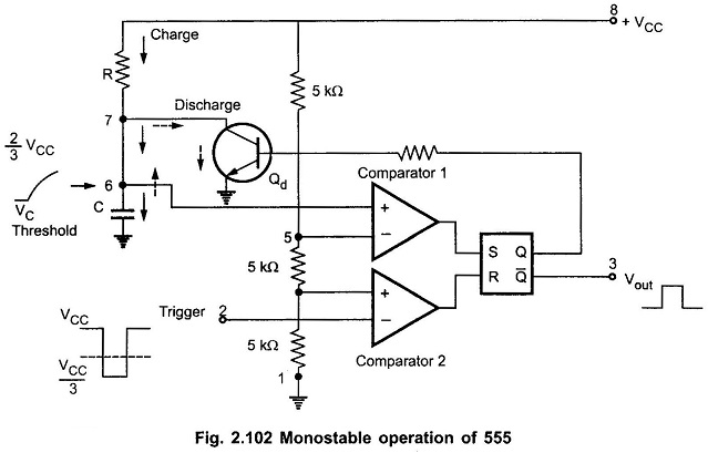
The circuit has only one stable state. When trigger is applied, it produces a pulse at the output and returns back to its stable state. The duration of the pulse depends on the values of R and C. As it has only one stable state, it is called one shot multivibrator.
Working of 555 Timer as Monostable Multivibrator:
The flip-flop is initially set i.e. Q is high. This drives the transistor Qd in saturation. The capacitor discharges completely and voltage across it is nearly zero. The output at pin 3 is low.
When a trigger input, a low going pulse is applied, then circuit state remains unchanged till trigger voltage is greater than 1/3 VCC. When it becomes less than 1/3 VCC, then comparator 2 output goes high. This resets the flip-flop so Q goes low and Q̅ goes high. Low Q makes the transistor Qd off. Hence capacitor starts charging through resistance R, as shown by dark arrows in the Fig. 2.102.
The voltage across capacitor increases exponentially. This voltage is nothing but the threshold voltage at pin 6. When this voltage becomes more than 2/3 VCC, then comparator 1 output goes high. This sets the flip-flop i.e. Q becomes high and Q̅ low. This high Q drives the transistor Qd in saturation. Thus capacitor C quickly discharges through Qd as shown by dotted arrows in the Fig. 2.103.
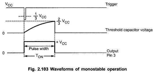
So it can be noted that Vout at pin 3 is low at start, when trigger is less than 1/3 VCC it becomes high and when threshold is greater than 2/3 VCC again becomes low, till next trigger pulse occurs. So a rectangular wave is produced at the output. The pulse width of this rectangular pulse is controlled by the charging time of capacitor. This depends on the time constant RC. Thus RC controls the pulse width. The waveforms are shown in the Fig. 2.103.
Derivation of Pulse Width:
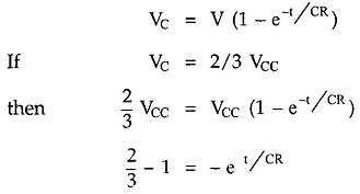
The voltage across capacitor increases exponentially and is given by
where
- C in farads,
- R in ohms,
- t in seconds.
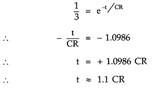
Thus, we can say that voltage across capacitor will reach 2/3 VCC in approximately 1.1 times, time constant i.e. 1.1 RC
Thus the pulse width denoted as W is given by,
![]()
Schematic Diagram:
Generally a schematic diagram of the IC 555 circuits is shown which does not include comparators, flip-flop etc. It only shows the external components to be connected to the 8 pins of IC 555. Thus, the schematic diagram of Monostable Multivibrator Using IC 555 is shown in the Fig. 2.104.
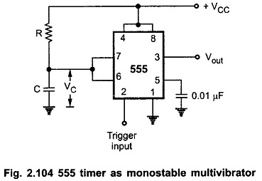
The external components R and C are shown. To avoid accidental reset, pin 4 is connected to pin 8 which is supply +VCC. To have the noise filtering of control voltage, the pin 5 is grounded through a small capacitor of 0.01 μF.
Monostable Multivibrator Using IC 555 Applications:
The various applications of Monostable Multivibrator Using IC 555 are,
- Frequency divider
- Pulse width modulation
- Linear ramp generator
- Pulse position modulation
- Missing pulse detector
- Timer in relay