What is Emitter Coupled Logic (ECL) Circuit?
Emitter coupled logic (ECL) is the fastest of all logic families and, therefore, is employed in applications where very high speed is essential. High speeds have become possible in ECL because the transistors are used in differential amplifier configuration, in which they are never driven into saturation and thereby the storage delay time is eliminated. Here, rather than switching the transistors from on to off and vice versa, they are switched between cutoff and active regions. It has propagation delay time of about 1 ns, which makes ECL a little faster than advanced Schottky TTL (74AS series). Another feature of ECL is that it provides two outputs which are always complement of each other. This is due to the fact that circuit operation is based on a differential amplifier. This feature eliminates the need for inverters. The logic levels are nominally -0.8 V and -1.7 V for the logics 1 and 0 respectively. Worst-case ECL noise margins are about 250 mV. These low noise margins make ECL somewhat unsuitable for use in heavy industrial environments.
Because of the low output impedance of the emitter follower and the high input impedance of the differential amplifier input, high fan-out (around 25) operation is possible. Since in this type of circuit, saturation is not possible, power consumption is increased (typically 40 mW) and voltage swing is limited (less than 1 V).
The total current flow in an Emitter Coupled Logic circuit remains relatively constant regardless of its logic state. This helps in maintaining an unvarying current drain on the circuit power supply even during switching transitions. Thus, no noise spikes are generated internally like those produced by TTL totem-pole circuits.
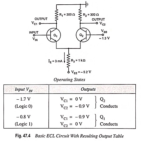
Basic Emitter Coupled Logic Circuit: The basic circuit for emitter coupled logic is essentially the differential amplifier configuration and is shown in Fig. 47.4. The emitter supply VEE produces an essentially fixed current IE (about 3 mA during normal operation). This current is allowed to flow through either transistor Q1 or transistor Q2, depending on the voltage level at the input (VIN). It means emitter current IE will switch between collectors of transistors Q1 and Q2 as VIN switches between its two logic levels of -1.7 V (logic 0 for ECL) and -0.8 V (logic 1 for ECL). This shows the resulting output voltage for these two input conditions. Here there are two noteworthy points : (1) The outputs VC1 and VC2 are the complements of each other, and (2) the output voltage levels are not the same as the input logic levels.
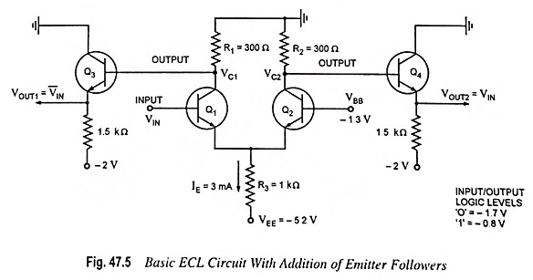
The second noteworthy point is easily taken care of by connecting outputs VC1 and VC2 to emitter follower stages Q3 and Q4, as illustrated in Fig. 47.5. The emitter followers perform two functions: (1) they subtract approximately 0.8 V from VC1 and VC2 to shift the output levels to the correct ECL logic levels and (2) they provide a very low output impedance (typically 7 Ω), which provides for large fan-out and fast charging of load capacitance. This circuit produces two complementary outputs VOUT1 and VOUT2 which are equal to V̅IN and VIN respectively.
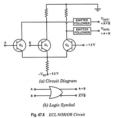
The basic Emitter Coupled Logic circuit shown in Fig. 47.5 can be used as an INVERTER if the output is taken at VOUT1. The basic circuit can be expanded to more than 1 input by paralleling transistor Q1 with other transistors for the other inputs, as illustrated in Fig. 47.6(a). Here either Q1 or Q3 can cause the current to be switched out of Q2, resulting in the two outputs VOUT1 and VOUT2 being the logical NOR and OR operations, respectively. The symbol of this OR/NOR gate is given in Fig. 47.6(b). This is the fundamental ECL gate.
The ECL family is not as widely used as the TTL and MOS families except in very high frequency applications. Low noise margins and high power drain are the drawbacks in comparison with other logic families. The other drawback is its negative voltage supply and logic levels, which are not compatible with other logic families. This makes it difficult to use ECL in conjunction with TTL and MOS circuits.