Logic Circuits Interview Questions and Answers:
1. What is a combinational circuit?
Ans. In a combinational circuit, the output depends upon present input(s) only i.e., not dependent on the previous input(s). The combinational circuit has no memory element. It consists of logic gates only.
2. Write two characteristics of combinational circuits.
Ans. The two characteristics of combinational circuits are:
- In combinational circuits, the output exists as long as the input exists.
- A combinational circuit will always respond in the same fashion to input function, when we apply signal to the input terminal of the combinational logic circuit.
3. Clearly differentiate between the following concept : Combinational and sequential circuits.
Ans. Logic circuit may be classified into two categories i.e., combinational logic circuits and sequential logic circuits. A combinational logic circuit contains logic gates only but does not contain storage elements. A sequential logic circuit contains storage elements in addition to logic gates.
In sequential logic circuits, output states of the circuits remain in their state, until instructed to change it, so it can be said that these circuits possess memory, while in combinational logic circuits, output state changes with the change in input state. In sequential logic circuits, stored output is applied to logic gates at proper places in circuits with feedback connections, therefore, such circuits are driven not only by the externally applied inputs but by the feedback signals also.
Adder, subtractor, encoder, decoder, MUX, DEMUX etc, fall under the category of combinational circuits, while FFs, counters etc. fall under the category of sequential circuits.
4. What is a half-adder?
Ans. A logic circuit, that can add two 1-bit numbers and produce outputs for sum and carry, is called a half-adder.
5. What is a full-adder?
Ans. A binary adder, which can add two 1-bit binary numbers along with a carry bit and produces outputs for sum and carry is called a full-adder.
6. What is the logic signal required to inhibit a NAND gate and what is its output when inhibited?
Ans. Logic 0 is the logic signal required to inhibit a NAND gate and 1 is its output, irrespective of all other inputs, when inhibited.
7. What is multiplexing?
Ans. Multiplexing is an operation performed with digital logic circuits called multiplexers and allows information to be switched from several lines into a single line in a specified sequence.
8. What is an encoder?
Ans. An encoder is a logic circuit that produces coded binary outputs from uncoded inputs.
9. What is a demultiplexer?
Ans. Demultiplexer is a logic circuit that accepts one data input and distributes it over several outputs.
10. What is a decoder?
Ans. Decoder is a logic circuit that decodes from binary to octal, decimal, hexadecimal, or any other code such as 7-segment circuit etc.
11. What are the applications of multiplexer?
Ans. Multiplexer have the applications of (i) data selection and routing (ii) operation sequencing, (iii) waveform generation, (iv) logic function generation, (v) parallel to serial conversion.
12. What is sequential circuit?
Ans. Sequential logic circuit is that circuit in which outputs of the circuit remain in their state, until instructed to change it. In other words sequential logic circuit may be defined as that logic circuit whose outputs are determined by the sequence in which input signals are applied.
13. What is a flip-flop?
Ans. A flip-flop is a basic memory element that is made of an assembly of logic gates and is used to store 1-bit of information.
14. What is a latch?
Ans. It is a D-type of flip-flop and stores one bit of data.
15. What is an excitation table?
Ans. Excitation table gives an information about what should be the flip-flop inputs if the outputs are specified before and after the clock pulses.
16. What is a state table?
Ans. State table consists of complete information about present state, next state, and outputs of a sequential circuit.
17. What two types of input does a clocked flip-flop have?
Ans. A clocked FF has two types of inputs—clocked pulse input and data input. The clock pulse is an activating signal that triggers the FF for operation. The data inputs are the binary information that affect the state of the FF.
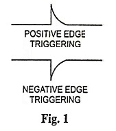
18. What is meant by edge triggering?
Ans. Edge triggering means activation of the clock input on the transitions of the clock pulse (edges of the clock pulse) rather than the entire duration of the clock pulse (levels of the clock pulse). There are two types of edge triggering, as shown in the Fig. 1.
19. Define set-up time and hold-time for a clocked flip-flop.
Ans. The set-up time (ts) is the time interval immediately preceding the active edge (transition) of the CLK signal during which the control input must be maintained at the proper level.
The hold time (tH) is the time interval immediately following the active edge (transition) of the CLK signal during which the synchronous control input must be maintained at the proper level.
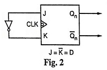
20. How can a D flip-flop be implemented using a J-K flip-flop.
Ans. D flip-flop can be implemented by connecting an inverter between inputs J and K, as shown in the Fig. 2.
21. What is Race-Around condition in a J-K flip-flop? Explain how it occurs. Suggest a method to overcome the race-around difficulty.
Ans. When both inputs J and K are low, the circuit is inactive with J low and K high, the circuit is reset when a positive clock edge strikes. Flip-flop remains in reset state with J = 1 and K = 0. The circuit is set at arrival of reset positive clock pulse when both inputs are high (i.e., J = 1 and K = 1), the flip-flop will toggle. This is known as race round condition.
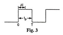
If pulse width of CLK (tp) is lesser than propagation delay of FF (Δt) and let the output change its state in Δt time interval.
So after Δt time duration, we have again condition J = K = 1 and CLK is high, output will again change its state i.e., output will oscillate back and forth between 0 and 1 in duration of tp and at the end of CLK pulse, value of output is ambiguous. trace-around condition can be avoided as follows:
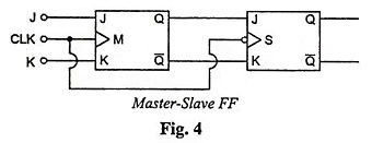
If tp ≤ Δt, lumped delay line can be used in series with feedback connection in order to enhance the loop delay or by using Master-slave FF.
22. What is meant by a counter?
Ans. Counter is a digital circuit which is used to count pulses and give the output in the binary form.
23. Clearly differentiate between the following concept:
Ans. In a synchronous counter all the flip-flops get clocked simultaneously where as in an asynchronous counter the output of one flip-flop drives another flip-flop.
Synchronous counter is faster and have no decoding error occurs while asynchronous counter is relatively slower and have decoding errors occur due to propagation delay.
24. What is a ripple counter?
Ans. When the output of one flip flop drives another flip-flop, the counter is called a ripple counter.
25. Why is a parallel counter faster than ripple counter?
Ans. In a ripple counter the output of one flip-flop drives another flip-flop while in a parallel counter all the flip-flops get clocked simultaneously. So parallel counter is faster than ripple counter.
26. What is counter MOD number?
Ans. MOD number of a counter is the number of possible states that it has.
27. What is a ring counter?
Ans. In a ring counter, the Q output of the flip-flop and the D input of the successive flip-flop are connected in such a way that it forms a ring.
28. What is decimal/decade counter?
Ans. A decimal/decade counter is a circuit of flip-flops in casade, which counts in decimal number system.