What is Tristate Logic or Three State Logic Circuit?
Tristate Logic or Three State Logic Circuit – In normal logic circuits there are two states of output, either low or high. But in complex digital systems like microcomputers and microprocessors, a number of gate outputs may be required to be connected to a common line which is referred to as a bus which in turn, may be required to drive a number of gate inputs. When a number of gate outputs are connected to the bus, some difficulties are encountered. These are:
- Totem-pole outputs cannot be connected together due to very large current drain from the supply and consequent heating of ICs which may get damaged.
- Open collector outputs can be connected together with a common collector resistor connected externally. This causes the problems of loading and operation speed.
To overcome these difficulties, special circuits have been developed in which there is one more state of output, referred to as the third state or high impedance (Hi-Z) state, in addition to low and high states. Such circuits are called Tristate or three state logic.
The tristate logic circuit utilizes the high speed operation of the totem-pole arrangement while permitting outputs to be wiredANDed (connected together). The Hi-Z state is a condition in which both transistors in the totem-pole arrangement are turned off so that the output terminal is a high impedance to ground and to VCC. In other words, the output is an open or floating terminal that is neither a low nor a high. In practice the output terminal is not an exact open circuit, but has a high resistance of several MΩ or more relative to ground and VCC.
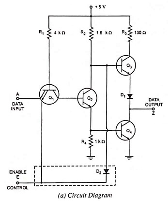
The tristate logic circuit operation is achieved by modifying the basic totem-pole circuit. Fig. 47.8 (a) shows the circuit for a tristate INVERTER where the portion enclosed in a dotted rectangle has been added to a basic circuit. The circuit has two inputs : A is the normal logic input and E is an ENABLE input capable of producing the Hi-Z state.
When E = 0, the circuit goes into its Hi-Z state regardless of the state of logic input A. The low at E forward-biases the emitter-base junction of transistor Q1 and shunts the resistor R1 current away from transistor Q2 so that Q2 turns off, which turns transistor Q4 off. The low at E also forward biases diode D2 to shunt current away from the base of transistor Q3, so that Q3 also turns off. With both totem-pole transistors in the off-state, the output terminal is essentially an open circuit. This is illustrated in Table 47.2 (truth table for TTL inverter).
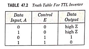
With E = 1, the circuit operates as a normal INVERTER because the high input at E has no effect on transistor Q1 or diode D2. In this enabled condition the output is simply the inverse of logic input; as illustrated in Table 47.2.
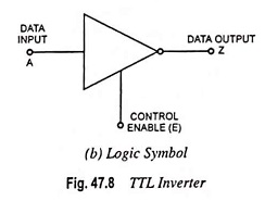
The logic symbol for the tristate inverter is shown in Fig. 47.8 (b).
Advantage of Tristate Logic Circuit:
The advantage of tristate ICs is that their outputs can be connected together (paralleled) without sacrificing switching speed. This is due to the fact that a tristate output, when enabled, operates as a totem-pole output with its associated low-impedance high-speed characteristic. It is important to realize, however, that when tristate outputs are paralleled, only one of them should be enabled at a time. Otherwise, two active totem-pole outputs would be connected together and damaging currents could flow.
Tristate devices are used in the bus design. A bus consists of a collection of distinct lines, serving different purposes. In a bus, outputs of different gates can be connected together. In a microprocessor based system, there is a data bus, address bus and control bus. The purpose is to transfer information from one gate to another. The three-state design enables faster data transfers.
When the control line is high, the gate is enabled and input is transferred to the output. When the control line is low, the gate is in high impedance (Hi-Z) state. In a bus, outputs of many tristate gates will be connected to one bus. The gate which is enabled will transfer data to the bus. The gate which is in Hi-Z state behaves as if it is not connected to the bus.