Three Phase Rectifiers:
Three-Phase Half-Wave Rectifier : Figure 9.11 illustrates a circuit for a 3-phase half-wave rectifier. The three diodes are connected to the three phases of a 3-phase transformer star-connected secondary. Neutral point N of the secondary forms the negative terminal for the load and is earthed, as illustrated in Fig. 9.11. Input and output waveforms are also shown in the figure. The effect of transformer leakage reactance and resistance are neglected as it is the anode forward voltage drop.
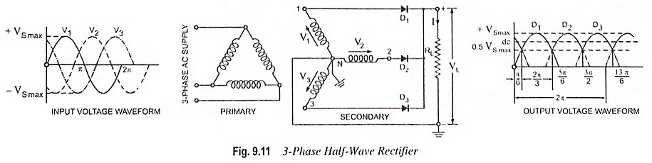
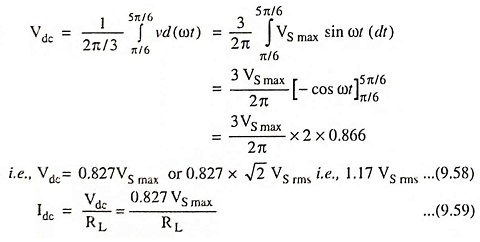
Each diode conducts during one-third of the cycle, as obvious from Fig. 9.11. When one diode conducts, the other two remain inactive because then their cathodes become positive with respect to their anodes. This process repeats itself during each ensuing cycle. The dc voltage (between cathode and neutral point) fluctuates between the peak value of alternating voltage per phase VS max and half of this value i.e., 1/2 VS max (neglecting diode voltage drops). DC output voltage can be obtained from the following equation
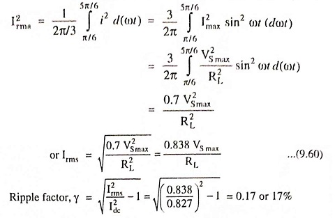
RMS value of load current can be obtained from the following equation
The above arrangement is very useful if 3-phase supply is available. Even with no smoothing arrangement there is no point at which the rectified voltage falls to zero, as it does acts in single phase circuits. The voltage ripple is comparatively small and has three times the frequency of the ac supply. Smoothing, if desirable, is much more easily achieved.
However, dc saturation of transformer core is caused due to flow of direct current of each diode in the transformer secondary phase windings, but it can be avoided by using zig-zag secondary.
Three-Phase Full-Wave Rectifier : The circuit for a 6-diode, 6-phase half-wave or three phase full-wave rectifier is shown in Fig. 9.12. Here each diode conducts only for one-sixth of the period i.e., π/3. Output waveform of a 6-diode rectifier is shown in Fig. 9.12. The dc voltage is seen to fluctuate less than for three phase. It varies between maximum alternating voltage (phase value) and 86.6 per cent of this, the average value being 0.955 times the maximum value.
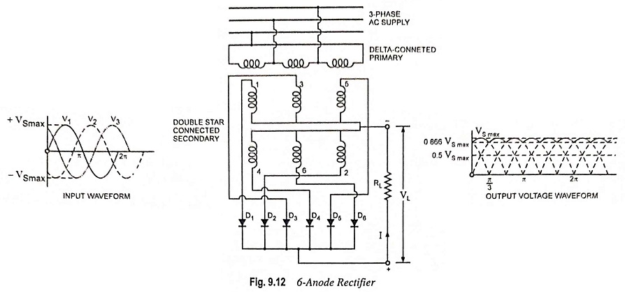
The advantage of using larger number of diodes is that output is much smoother. The disadvantages of using a large number of diodes are that each diode operates for a shorter time per cycle and construction becomes complicated. The most advantageous number is 6, since if more than 6 diodes are used, then cost increases rapidly without a comparative increase in the output of the rectifier.
Use of Interphase Transformer : The factors to govern the number of phases for which a rectifier is to be designed are (1). low harmonic generation in the output circuit (2). better transformer utilization factor (3). low voltage regulation and (4). high power factor. The condition 1 requires that the number of phases should be high, but to fulfil conditions 2, 3 and 4 it is necessary that the number of phases be kept low.
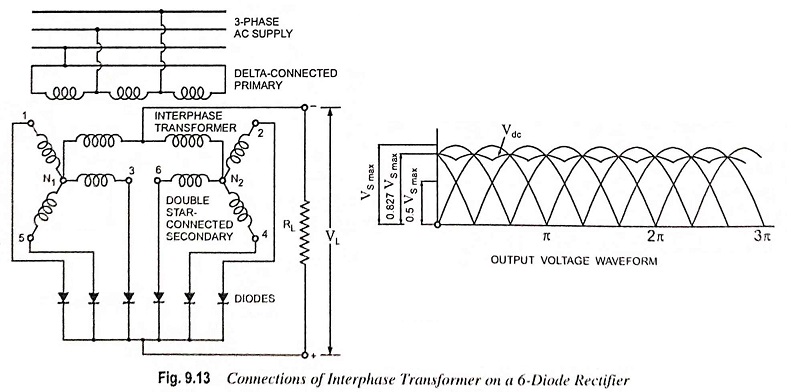
The advantages of a 3-phase rectifier such as better transformer utilization factor, high power factor and low voltage regulation and advantage of 6-phase or 12-phase rectifier of low harmonic percentage can be had together by using interphase transformer with 6- or 12-diode rectifier. In this modified scheme m diodes for a rectifier are split into a number of star-connected groups of three e.g. two groups for a 6-diode and four groups for a 12-diode rectifier. Each diode group has its own individual secondary winding, the star points of the various groups, instead of being directly connected together, are connected through an interphase transformer. The common neutral point forms the -ve terminal of the dc output circuit.
The function of the interphase transformer in the above scheme is to equalize potential of two diodes at a time so that at any given instant the load is shared by those two diodes which are effectively working in parallel. Thus, although the output dc voltage waveform has the characteristic of a 6-phase rectifier with its low harmonic content of twice the supply frequency, the load is actually shared by two 3-phase systems operating in parallel at a terminal voltage which is the mean of the terminal voltages of the phases operating together. Each phase of the transformer operates for one-third of the cycle instead of one-sixth and mean output voltage is the same as that of a rectifier with three diodes instead of six. The mean dc voltage obtained is 1.17 VS rms or 0.827 VS max less the diode voltage drop which is identical with that obtained from a 3-phase, 3-diode rectifier.
KVA rating of interphase transformer is given equal to 0.0805 Vdc Idc x 10-3.
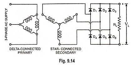
Three Phase Bridge Rectifier : This circuit is commonly used because it is very simple and does not need centre-tap transformer. In this circuit load current Idc is 0.955 times the peak current through each diode and Vdc is 2.34 times the rms ac voltage across each secondary leg (twice that in a 3-Φ half-wave rectifier). Each diode carries only one-third of load current Idc (rather than one-sixth, as in Fig. 9.12).