Three Phase Service Cable:
In practice, underground cables are generally required to deliver 3-phase power. For the purpose, either three-core cable or three single core cables may be used. For voltages upto 66 kV, 3-core cable multi-core construction) is preferred due to economic reasons. However, for voltages beyond 66 kV, 3-core-cables become too large and unwieldy and, therefore, single-core cables are used. The following types of cables are generally used for Three Phase Service Cable:
- Belted cables — upto 11 kV
- Screened cables — from 22 kV to 66 kV
- Pressure cables — beyond 66 kV
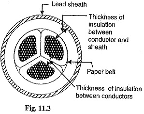
1.Belted cables: These cables are used for voltages upto 11kV but in extraordinary cases, their use may be extended upto 22kV. Fig. 11.3 shows the constructional details of a 3-core, belted cable. The cores are insulated from each other by layers of impregnated paper. Another layer of impregnated paper tape, called paper belt is wound round the grouped insulated cores. The gap between the insulated cores is filled with fibrous insulating material (jute etc.) so as to give circular cross-section to the cable. The cores are generally stranded and may be of non-circular shape to make better use of available space. The belt is covered with lead sheath to protect the cable against ingress of moisture and mechanical injury. The lead sheath is covered with one or more layers of armouring with an outer serving (not shown in the figure).
The belted type construction is suitable only for low and medium voltages as the electrostatic stresses developed in the Three Phase Service Cable for these voltages are more or less radial i.e., across the insulation. However, for high voltages (beyond 22 kV), the tangential stresses also become important. These stresses act along the layers of paper insulation. As the insulation resistance of paper is quite small along the layers, therefore, tangential stresses set up leakage current along the layers of paper insulation. The leakage current causes local heating, resulting in the risk of breakdown of insulation at any moment. In order to overcome this difficulty, screened cables are used where leakage currents are conducted to earth through metallic screens.
2.Screened cables: These cables are meant for use upto 33 kV, but in particular cases their use may be extended to operating voltages upto 66 kV. Two principal types of screened cables are H-type cables and S.L. type, cables.
(i) H-type cables: This type of Three Phase Service Cable was first designed by H. Hochstadter and hence the name. Fig. 1.1.4 shows the constructional details of a typical 3-core, H-type cable. Each core is insulated by layers of impregnated paper. The insulation on each core is covered with a metallic screen which usually consists of a perforated aluminium foil. The cores are laid in such a way that metallic screens make contact with one another. An additional conducting belt (copper woven fabric tape) is wrapped round the three cores. The Three Phase Service Cable has no insulating belt but lead sheath, bedding,armouring and serving follow as usual. It is easy to see that each core screen is in electrical contact with the conducting belt and the lead sheath. As all the four screens (3 core screens and one conducting belt) and the lead sheath are at tearth potential, therefore, the electrical stresses are purely radial and consequently dielectric losses.
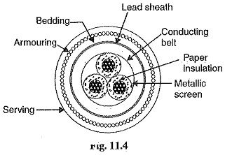
Two principal advantages are claimed for H-type cables. Firstly, the perforations in the metallic screens assist in the complete impregnation of the Three Phase Service Cable with the compound and thus the possibility of air pockets or voids (vacuous spaces) in the dielectric is eliminated. The voids if present tend to reduce the breakdown strength of the cable and may cause considerable damage to the paper insulation. Secondly, the metallic screens increase the heat dissipating power of the cable.
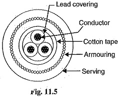
(ii) S.L. type cables: Fig. 11.5 shows the constructional details of a 3-core S.L. (separate lead) type cable. It is basically H-type cable but the screen round each core insulation is covered by its own lead sheath. There is no overall lead sheath but only armouring and serving are provided. The S.L. type cables have two main advantages over H-type cables. Firstly, the separate sheaths minimize the possibility of core-to-core breakdown. Secondly, bending of cables becomes easy due to the elimination of overall lead sheath. However, the disadvantage is that the three lead sheaths of S.L. cable are much thinner than the single sheath of H-cable and, therefore, call for greater care in manufacture.
Limitations of solid type cables: All the cables of above construction are referred, to as solid type cables because solid insulation is used and no gas or oil circulates in the cable sheath. The voltage limit for solid type cables is 66 kV due to the following reasons :
(a) As a solid Three Phase Service Cable carries the load, its conductor temperature increases and the cable compound (i.e., insulating compound over paper) expands. This action stretches the lead sheath which may be damaged.
(b) When the load on the cable decreases, the conductor cools and a partial vacuum is formed within the cable sheath. If the pinholes are present in the lead sheath, moist air may be drawn into the The moisture reduces the dielectric strength of insulation and may eventually cause the breakdown of the cable.
(c) In practice, tvoids are always present in the insulation of a cable. Modern techniques of manufacturing have resulted in void free cables. However, under operating conditions, the voids are formed as a result of the differential expansion and contraction of the sheath and impregnated compound The breakdown strength of voids is considerably less than that of the insulation. If the void is small enough, the electrostatic stress across it may cause its breakdown. The voids nearest to the conductor are the first to break down, the chemical and thermal effects of ionisation causing permanent damage to the paper insulation.
3.Pressure cables: For voltages beyond 66 kV, solid type cables are unreliable because there is a danger of breakdown of insulation due to the presence of voids. When the operating voltages are greater than 66 kV, pressure cables are used. In such cables, voids are eliminated by increasing the pressure of compound and for this reason they are called pressure cables. Two types of pressure cables viz oil-filled cables and gas pressure cables are commonly used.
(i) Oil-filled cables: In such types of cables, channels or ducts are provided in the cable for oil circulation. The oil under pressure (it is the same oil used for impregnation) is kept constantly supplied to the channel by means of external reservoirs placed at suitable distances (say 500 m) along the route of the Three Phase Service Cable. Oil under pressure compresses the layers of paper insulation and is forced into any voids that may have formed between the layers. Due to the elimination of voids, oil-filled cables can be used for higher voltages, the range being from 66 IN upto 230 kV. Oil-filled cables are of three types viz., single-core conductor channel, single-core sheath channel and three-core filler-space channels.
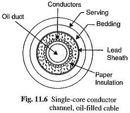
Fig. 11.6 shows the constructional details of a single-core conductor channel, oil filled cable. The oil channel is formed at the centre by stranding the conductor wire around a hollow cylindrical steel spiral tape. The oil under pressure is supplied to the channel by means of external reservoir. As the channel is made of spiral steel tape, it allows the oil to percolate between copper strands to the wrapped insulation. The oil pressure compresses the layers of paper insulation and prevents the possibility of void formation. The system is so designed Conductors that when the oil gets expanded due to increase in cable temperature, the extra oil collects in the reservoir. However, when the cable temperature falls during light load conditions, the oil from the reservoir flows to the channel. The disadvantage of this type of cable is that the channel is at the middle of the Three Phase Service Cable and is at full voltage w.t: t. earth, so that a very complicated system of joints is necessary.
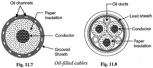
Fig. 11.7 shows the constructional details of a single core sheath channel oil-filled cable. In this type of cable, the conductor is solid similar to that of solid cable and is paper insulated. However, oil ducts are provided in the metallic sheath as shown in Fig. 11.8, the oil ducts are located in the filler spaces. These channels are composed of perforated metal-ribbon tubing and are at earth potential.
The oil-filled cables have three principal advantages. Firstly, formation of voids and ionisation are avoided. Secondly, allowable temperature range and dielectric strength are increased. Thirdly, if there is leakage, the defect in the lead sheath is at once indicated and the possibility of earth faults is decreased. However, their major disadvantages are the high initial cost and complicated system of laying.
(ii) Gas pressure Cables: The voltage required to set up ionisation inside a void increases as the pressure is increased. Therefore, if ordinary cable is subjected to a sufficiently high pressure, the ionisation can be altogether eliminated. At the same time, the increased pressure produces radial compression which tends to close any voids. This is the underlying principle of gas pressure cables.
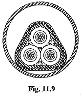
Fig. 11.9 shows the section of external pressure cable designed by Hochstadter, Vogal and Bowden. The construction of the cable is similar to that of an ordinary solid type except that it is of triangular shape and thickness of lead sheath is 75% that of solid cable. The triangular section reduces the Weight and gives low thermal resistance but the main reason for triangular shape is that the lead sheath acts as a pressure membrane. The sheath is protected by a thin metal tape. The Three Phase Service Cable is laid in a gas-tight steel pipe. The pipe is filled with dry nitrogen gas at 12 to 15 atmospheres. The gas pressure produces radial compression and doses the voids that may have formed between the layers of paper insulation. Such cables can carry more load current and operate at higher voltages than a normal cable. Moreover, maintenance cost is small and the nitrogen gas helps in quenching any flame. However, it has the disadvantage that the overall cost is very high.