Construction of Optical Fiber Cable:
The manufacture and Construction of Optical Fiber Cable are somewhat complicated: In simple terms, a highly refined quartz tube that will eventually be filled with a combination of gases (silicon, tetrachloride, germanium tetrachloride, phosphorus oxychloride) is selected to start the process. This tube, about 4 ft long and about 1 in. in diameter, is placed in a lathe and the gases are injected into the hollow tube. The tube is rotated over a flame and subjected to temperatures of about 1600°F. The burning of the gases produces a deposit on the inside of the tube. This preform (quartz tube with gas deposit) is then heated to about 2100°F, melting and collapsing the tube to about 13 mm. The preformed quartz is now ready to be placed in the vertical drawing tower (see Figure 18-12).
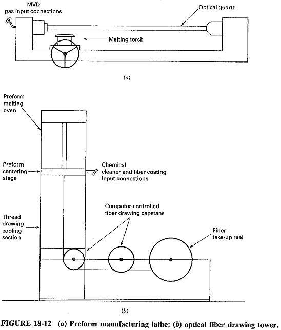
The quartz rod, having undergone the modified chemical vapor deposition (MCVD) process, is now placed vertically in a drawing tower where it is further heated (2200°F) and drawn downward by means of a computer-controlled melting and drawing process which produces a fine, high-quality fiber thread approximately 125 μm in diameter and about 6.25 km in length. The optically pure center, called the core (as small as 8 μm in diameter) is surrounded by less optically pure quartz called the Cladding. The cladding is approximately 117 µm of boundary material formed during MCVD process.
All data concerning the Construction of Optical Fiber Cable is then measured (bandwidth, refractive index, cladding thickness, timed reflectometer response, and so on) and recorded. This data is stored with the spool of fiber as a permanent record. The Construction of Optical Fiber Cable is coated during the drawing process with polyethylene or epoxy for protection, and in some instances color coding is applied, according to the users’ needs.
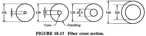
A typical cross section of a single-strand fiber is shown in Figure 18-13. The Construction of Optical Fiber Cable basically consists of two concentric layers, the light-carrying core (50 μm) and the cladding. The cladding acts as a refractive index medium (light bending) and allows the light to be transmitted through the core and to the other end with very little distortion or attenuation.
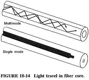
Figure 18-14 illustrates this action: light is introduced into the fiber, and the cladding refracts or reflects the light in a zigzag pattern throughout the entire length of the core. This process is possible because the angle of incidence and the angle of reflection are equal. Light introduced at such a sharp angle will strike the cladding (at a less than critical angle) and will be lost in the cladding material. The finished Construction of Optical Fiber Cable is shown in Figure 18-13 and consists of the following:
- The core n1
- The cladding n2
- The polymer jacket (applied by the fiber manufacturer to protect the core and cladding)
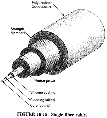
The fiber is now ready for the next processes, which will incorporate it into a single-fiber cable or a multi-fiber cable (see Figure 18-15). The basic single-fiber cable consists of the following:
- Core-quartz
- Cladding-silica
- Jacket-acrylic
- Buffer jacket
- Strength member
- Outer jacket
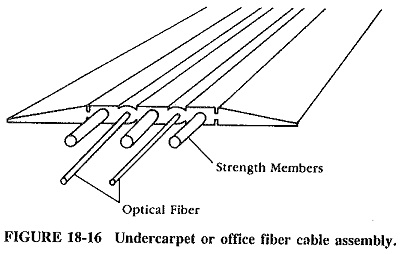
Depending on their application, multifiber cables are manufactured in many forms, from round cables of loose tight bundles, to specialized cables for use underwater, to flat overcarpet or undercarpet applications for business offices (see Figure 18-16).