Fiber Optic Components and Systems:
The Fiber Optic Components and Systems can be divided into subgroups, the source, the link, and the detectors. We will now explore the makeup and role of each of these groups.
The Source:
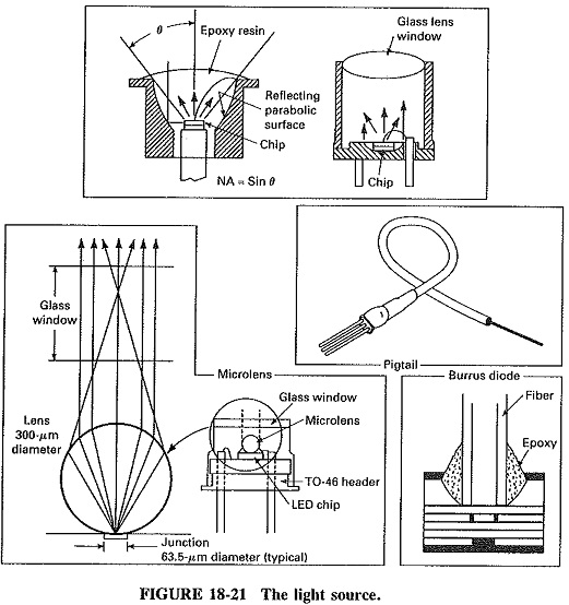
The source usually consists of a light-emitting element which is triggered or actuated by an electronic or electrical signal, for example, PIN photodiodes, light-emitting diodes (LEDs), avalanche photodiodes, and semiconductor lasers. When a source to match a fiber link is selected, particular attention must be paid to the wavelength specifications, the bandwidth, and the power output of the source so that efficient coupling and maximum power transfer can be achieved (see Figure 18-21).
Noise:
A noise also has an effect on optoelectronic systems, just as it does on electronic systems. As a quick refresher, some of the terms, we learned were:
-
Shot noise (noise created by uneven streams of electron flow)
-
Thermal noise (noise generated in resistive elements)
The term dark current noise should be added to the above. It is thermal noise generated by minute current flow in diodes. Later in this chapter, we will see how this noise factor is used.
Response Time:
As with noise, response time should be considered a limiting factor when an optical source is chosen. Response (rise) time is defined as the time between the 10 and 90 percent points. It is the time a device takes to convert electronic energy to light energy or vice versa (5 to 10 ns).
Response time affects the overall bandwidth of the device and can be approximated by Equation (18-9).

where
BW = bandwidth
tr= response time
As with other devices, the RC time constants affect the bandwidth of the device and can be calculated as shown in Equation (18-10).

where
RL = load resistance
Cd = diode capacitance
To determine the RL for this diode (so as not to lower the bandwidth), we must calculate the highest value possible, for example: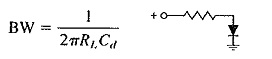
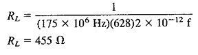
In practice, a value approximately 25 percent of this calculated value will be used. In general, the main characteristic difference between a source and a detector is the spectral width (source has narrow width) and output power (source has greater output power).
The Optical Link:
The optical link (the fiber and its physical characteristics were discussed at length at the beginning of this chapter) is the connection between the source and the detector. This part of the system usually consists of more than just the fiber cable. Some other devices in the system are (see Figure 18-22):
-
Fused tapered couplers
-
Beam-splitting couplers
-
Reflective star couplers
-
Optical multiplexers
-
Optical demultiplexers
-
Dichroic filters
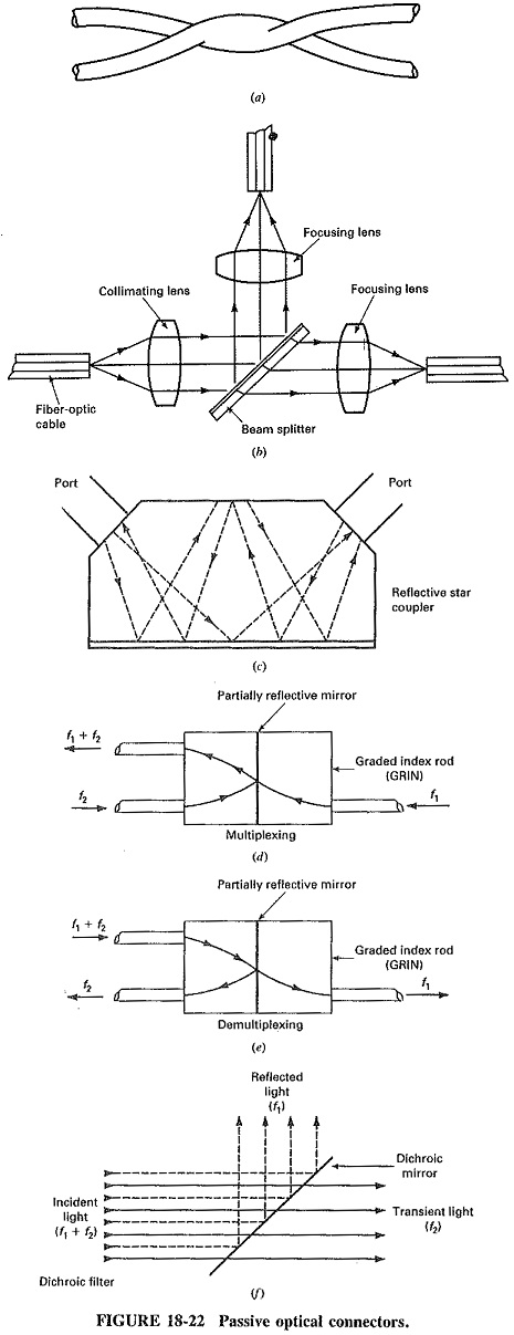
Fused couplers are constructed of a group of fibers fused by heat to form a single large fiber at the junction. Light introduced into any one of the fibers will appear at the ends of all the others.
Beam-splitting couplers are composed of a series of lenses and a (beam-splitting) partly reflective surface. The diffused light reflected and refracted by the reflecting surface would be useless without the collimating and focusing lenses.
A reflective star coupler, as shown in Figure 18-22, is a multiport reflective devise used to network computers and so forth.
So far the devices discussed have been used for dividing a light signal source into multiple outputs. Each time a signal is divided, its output power is diminished and coupling losses occur (approximately 0.5 dB per coupling). Therefore, if there is one input and two outputs, the power is split between outputs (3 dB per output port). Add to this the connector loss, and the sum of losses becomes a somewhat limiting factor (3.5 dB per output) often determined by the sensitivity of the detector.
Light Wave:
Light wave receivers or detectors are the final device in our basic optical communications system. These detectors are usually low-power, low-noise PIN diodes coupled to a FET amplifier.
The main consideration in the choice of detectors should be responsivity. This term describes the ratio of the diode’s output current to the input optical power and can be expressed as shown in Equation (18-13).
where
R = responsivity (A/W)
μW = incident light
μA = diode current
The noise characteristics and response time (BW) should be considered but can be approached the same way as the light source.
Many other optical devices perform various specific functions and are too numerous to be mentioned here. The last one we will discuss is the wavelength-division multiplexer (WDM). As shown in block form in Figure 18-22 the WDM uses a passive optical filtering system to solve the problem of multiplexing and demultiplexing. WDM is similar in concept and action to frequency-division multiplexing (FDM).
This task is accomplished in the optical environment by using a combination of diffraction grating and Dichroic Filtering. The action of reflection and refraction off and through the series-parallel surfaces combines the frequencies n1,n2 and n3 to become n1 + n2 + n3. The reverse is accomplished by using a dichroic (a coating substance which separates different wavelengths) coating on a special type of splice on the Fiber Optic Components and Systems themselves. This action is similar in function to that of a prism.
The System:
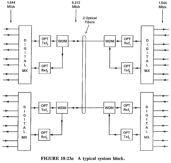
The complete system is a combination of all the components and processes so far discussed in this chapter and previous chapters. The incredible information-handling capabilities of the single-mode fiber make it highly suitable to the field of digital communications, where it has become the primary carrier of this type of information, not only in the broadband communications arena but also the digital computer field.
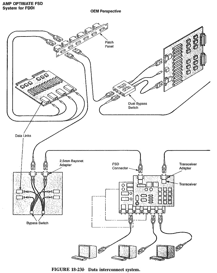
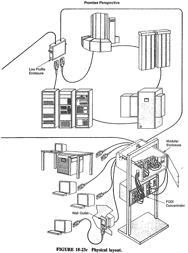
In simple terms, the system consists of the optical interface devices, the optical link, and the electronic transmitters and receivers. We can think of the transmitters and receivers as either broadband voice communications devices or digital computers (refer to Figure 18-23). To accomplish the interface portion of the system, the fiber industry has manufactured devices which can be retrofitted to most (computer or communications) existing equipment. A complete listing of this equipment and its specifications is available to the design engineer from the AMP Corporation, the Tektronix Corporation, or any other major manufacturer of Fiber Optic Components and Systems.
A list of optical components used to interconnect a digital voice or data system might include:
- Transceivers-for either simplex or duplex operation
- Receivers-for digital data or voice communications
- Transmitters-for digital data or voice communications
- Channel multiplexers—WDM
- Optical switching modules—FDDI
- Single-mode fiber cable—low-loss voice communications
- Multimode fiber cable—local area networks (LANs), and so forth
Add to this list the multitude of couplers, connectors, junction boxes, test equipment, and fiber-splicing devices available, and the system becomes a simple process of matching requirements and the available hardware.
Some design considerations include the following.
- The length of fiber cabling-attenuation, and so forth
- The source wavelength-type of fiber to be selected
- Interconnect losses-power budgeting
- Data rate-bandwidth of fiber and optoelectronic interface equipment
- Type of fiber-high-density, single-mode 100 Mbyte/s