PLC Hardware Components:
1. PLC Hardware Components – The input and output interface modules consists of an I/0 rack and individual I/O modules. Input interface modules, accept signals from the machine or process devices (120V ac) and convert them into signals (5V dc) that can be used by the controllers. Output interface modules convert controller signals (5V dc) into external signals of 120V ac used to control the machine or process.
In large PLC Hardware Components, I/0 sub system can be remotely located from the CPU. A remote subsystem is usually a rack type enclosure in which the I/0 modules are installed. An interconnecting cable allows communication between the processor and the rehiote 110 rack.
The location of a module within a rack and the terminal number of a module to which an input or output device is connected will determine the device,s address. Each input and output device must have a specific address.
This address is used by the process to identify where the device is located in order to monitor or control it. In addition, there is some means of connecting field wiring on the I/O module housing. Connecting the field wiring to the I/O housing allows easier disconnection and reconnection of the wiring in order to change modules. Lights are also added to each module to indicate the ON or OFF status of each I/O circuit. Most output modules also have blown fuse indicators.
A standard I/O module consists of a printed circuit board (PCB) and terminal assembly. The PCB contains the electronic circuitry used to interface the circuit of the processor with that of the input or output device. It is designed to plug into a slot or connector in the I/O rack or directly into the processor. The terminal assembly, which is attached to the front edge of the PCB is used for making field wiring connections.
2.Discrete I/O Modules
The most common type of I/0 interface module is the discrete type. This type of interface connects field input devices of the ON/OFF nature such as selector switches, push buttons and limit switches. Similarly output control is limited to devices such as lights, small motors, solenoids and motor starters that require simple ON/OFF switching.
Each discrete I/O module is powered by some field supplied voltage source. Since these voltages can be of different magnitude or type, I/O modules are available at various ac and dc voltage rating as listed in Table 21.1.
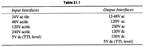
Figure. 21.70 shows a block diagram for one input of a typical ac interface input module.
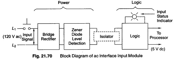
The input circuit is composed of two basic sections—the power section and the logic section. The power and logic sections are normally coupled together in a circuit, which electrically separates the two.
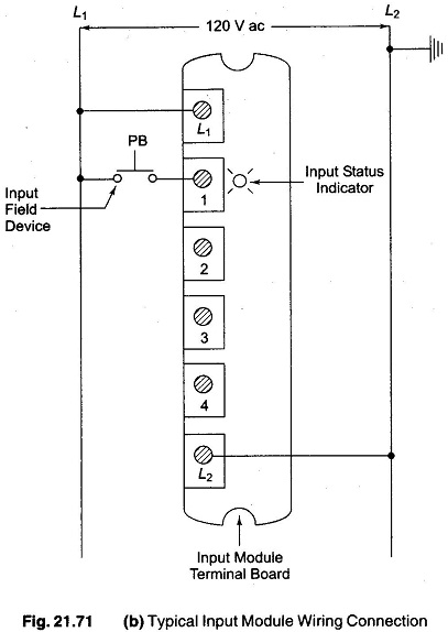
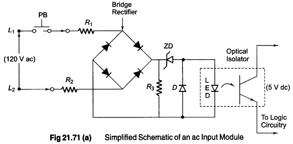
A simplified schematic and wiring diagram for one input of a typical ac input module is shown in Fig. 21.71(a) and (b). When the push button is closed, 120V ac is applied to the bridge rectifier through’ R1 and R2. This produces a low level dc voltage which is applied across the LED of the optical isolator. The Zener diode (ZD ) voltage rating sets the minimum level of voltage that can be detected . When the light from the LED strikes the photo transistor, it switches into conduction and the status of the push button is communicated in logic or low level dc voltage to the processor. The optical isolator not only separates the higher ac input voltage from the logic circuits, but also prevents damage to the processor due to line voltage transients.
Optical isolation also helps reduce the effects of electrical noise, common in industrial environment which can cause erratic operation of the processor. Coupling and isolation can be accomplished by use of a pulse transformer.
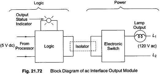
Figure. 21.72 shows a diagram for one output of a typical interface output module. Similar to the input module, it is composed of two basic sections, the power section and the logic section, coupled by an isolation circuit. The output interface can be considered of as a simple electronic switch to which power is applied to control output device.
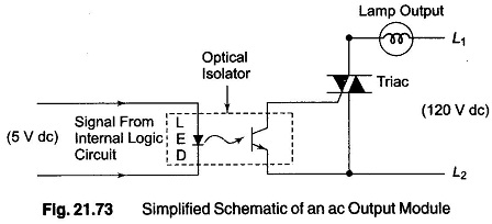
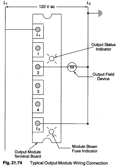
A simplified schematic and wiring diagram for one output of a typical ac output module is shown in Fig. 21.73. As part of its normal operation, the processor sets the output states according to the logic program. When the processor calls for an output, a voltage is applied across the LED of the isolator. The LED then emits light which switches on the phototransistor into conduction. This, in turn, switches a semiconductor switch such as Triac into conduction which turns on the lamp. Since the triac conducts in either direction, the output to lamp is ac. The triac rather than having ON and OFF status, actually has low and high resistance levels respectively. In its OFF state (high resistance) a small leakage current of a few mA still flows through the triac. As with input circuits, the output interface is usually provided with LED’s that indicate the status of each output. In addition, if the module contains a fuse, a fuse status indicator may also be used as shown in Fig. 21.74.
Individual ac outputs are usually limited by the size of the triac to 2 or 3A. The maximum current load for any one module is also specified. To protect the output module circuits, specified current ratings should not be exceeded.
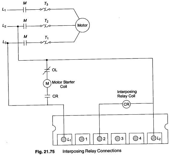
For controlling large loads, such as large motors, a standard control relay is connected to the output module. The contacts of the relay can then be used to control a large load or motor starter as shown in Fig. 21.75. When a control relay is used in this manner it is called an interposing relay.
3.Analog I/O modules
Earlier PLCs were limited to discrete I/O interfaces, which allowed only ON/ OFF type devices to be connected. This limitation meant that the PLC Hardware Components could have only partial control of many process applications. Today, however a complete range of both discrete and analog interfaces are available that will allow the controller to be applied to practically any type of the control process.
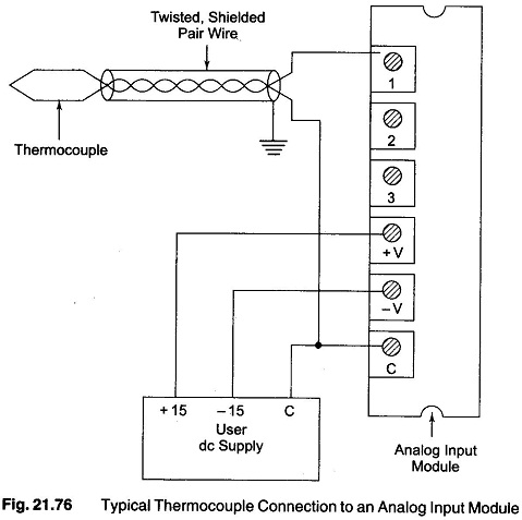
Analog input interface modules contain the circuitry necessary to accept analog voltage or current signals from analog field devices. These inputs are converted to digital by the use of an analog to digital converter (ADC). The conversion value, which is proportional to the analog signal, is expressed as a 12 bit binary or as a 3-digit BCD for the use by the processor. Analog input sensing devices include temerature, light, speed, pressure and position transducers. Figure 21.76 shows a typical analog input interface module connection to a thermocouple. A varying dc voltage in mV range proportional to the temperature being monitored, is produced by the thermocouple. This voltage is then amplified and digitized by the analog input module and then sent to the processor on command from a program instruction. Because of the low voltage level of the input signal, a shielded cable is used in wiring the circuit to reduce unwanted electrical noise signals that can be induced in the conductors from other wiring. This noise can cause temporary operating errors that can lead to hazardous or unexpected machine operation.
The analog output interface module receives from the processor digital data which is converted into a proportional voltage or current to control an analog field device. The digital data is passed through a DAC circuit to produce the necessary analog form. Analog output devices include small motors, valves, analog meters and seven segment displays.
4.T/O Specifications
Manufacturer’s specifications provide much information about how an interface device is correctly and safely used. The specification places certain limitation, not only on the module, but also on the field equipment that it can operate. The following is a list of some typical manufacturer, I/O specifications.
1.Nominal input voltage: This ac or dc value specifies the magnitude and type of voltage signal that will be accepted.
2.On state input voltage range: This value specifices the voltage at which input signal is recognized as being absolutely on.
3.Nominal current per input: This value specifies the minimum input current that the input devices must be capable of driving to operate the input circuit.
4.Ambient temperature rating: This value specifies what the maximum temperature, of the air surrounding the I/O module, should be for best operating conditions.
5.Input delay: This value specifies the time duration for which input signal must be ON before being recognized as a valid input. This delay is a result of filtering circuitry provided to protect against contact bounce and voltage transients. This input delay is typically in the 9 ms to 25 ms range.
6.Nominal output voltage: This ac or dc value specifies the magnitude and type of voltage source that can be controlled by the output.
7.Output voltage range: This value specifies the minimum and maximum output operating voltages. An output circuit rated at 120V ac, for example may have an absolute working range of 92 V ac (min) to 138 V ac max.
8.Maximum output current rating per output and module: These values specify the maximum current that a single output and the module as a whole can safely carry under load (at rated voltage).
9.Maximum surge current per output : This value specifies the maximum in rush current and duration (for example 20A for 0.1 second) for which an output circuit can exceed its maximum continuous current rating.
10.Off-state leakage current per output: This value specifies the maximum value of leakage current that flows through the output in its OFF state.
11.Electrical isolation: This maximum value (volts) defines the isolation between the I/O circuit and controller’s logic circuitry. Although this isolation protects the logic side of the module from excessive input or output voltage or current, the power circuitry of the module may be