PLC Basic Process:
A PLC Basic Process is basically made up of the following sections, each of which has a unique function to perform in its operation. The sections are:
- Sensing inputs or controlling hardware
- PLC input hardware
- Controller or CPU
- Hand held programming device or personal computer
- Output PLC hardware
- Hardware output devices
- Sensing Input: The sensing section consists of limit switches, pressure switches, photoelectric sensors, push buttons, etc. These incoming hardware devices provide input signals. Devices such as the push button, limit switch or photo-electric sensors are field input devices. The term field input refers to hardware items which provide the incoming signals that you physically connect to the PLC.
- Input Section: The input section of the PLC Basic Process contains two major areas. First, the physical contact (screw) terminals where the incoming signals (input) from field input devices such as a pressure switches are attached to the PLC.
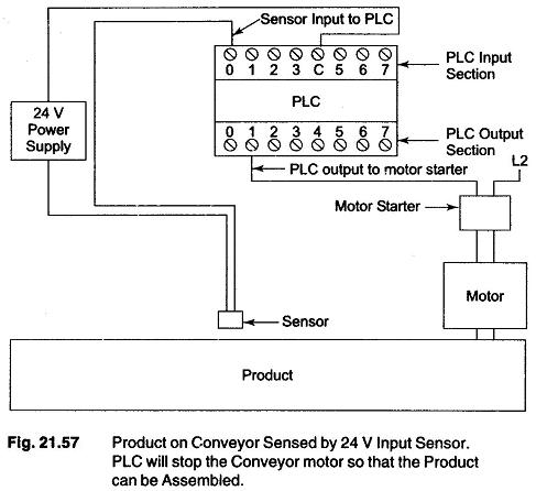
Figure 21.57 illustrates a product sitting on a conveyor. When the conveyor moves the product into position the sensor will send an input signal into input screw terminal number 0 on the PLC input section.
The second part of the input section is the PLC’ s internal conversion electronics. The function of the input section electronic component is to convert and isolate the high voltage input level from field devices.
High voltage signals from the field devices are converted to +5 V direct current V DC for a valid ON input signal and OV DC for a valid OFF input signal. Incoming signal conversion and isolation are necessary as the solid state microprocessor components operate on +5V dc, where as input signal may be 24 V dc, 110V ac or 220V dc.
- Controller: The controller, commonly called CPU (Central Processing Unit) or simply the processor. The processor controls or supervises the entire process. The CPU solves the user program and updates the status of the outputs.
- Programmer: The programmer is the device whereby the programmer or operator can enter or edit program instruction or data. The programmer can be a handheld unit, a PC or an industrial computer programming terminal.
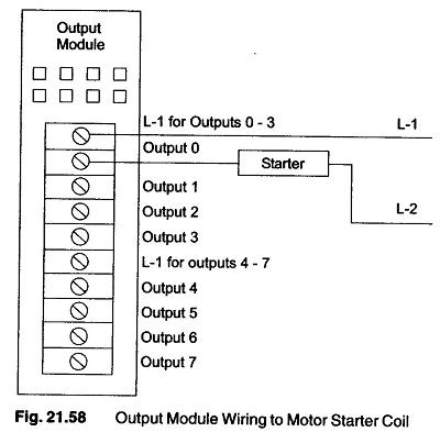
- Output Section: The result of the process whereby the CPU will look at, or read the status of inputs and then use this information to solve user program instructions is a series of outgoing signals from the CPU to an outside device such as a motor starter. These outgoing ON or OFF signals are known as outputs. Output signals are electronically transferred from the CPU to the output section electronics controlling the physical screw terminals on the output section of the PLC. (The PLC program for the application of Fig. 21.57 will be written to instruct the PLC to turn OFF the conveyor motor when a part is in position. The PLC will turn OFF the motor by turning OFF the output signal for the output Number 1 in the PLC output section.
- Field Hardware Devices: The PLC Basic Process will stop the conveyor motor when the product is sensed. The conveyor motor starter’s coil, which is