Signal Conditioning of Inputs:
Since all the data that have to be acquired, do not generally originate from identical sources, signal conditioning becomes necessary in some cases.
A simple attenuator, is used to scale down the input gains, this is to match the input signal level to the converter’ full scale range.
Linearisation of the data, for example from the thermocouple Wheatstone’s bridge, is performed by analog techniques using either linear-approximation, or smooth series approximation using a low cost IC amplifier.
Alternately linear approximation can be performed digitally after data acquisition and conversion by the use of ROMs (storing a suitable linearisation table or programme initially).
Analog differentiation, precision rectification and averaging, phase detection, logarithmic conversion, ratio computation using dividers and many other types of processors are used, before DAS.
Two methods of signal conditioning which are particularly applicable with advantage to data acquisition are
- Ratiometric conversion, and
- Logarithm conversion.
Ratiometric Conversion:
Consider a transducer using four strain gauges in a Wheatstone’s bridge. The output voltage is a function of the change in resistance of the strain gauge in each of the four arms, and the excitation voltage of the bridge.
If the strain gauges are under maximum but constant unbalance and if the excitation varies by ± x%, the output of the bridge also varies by ± x%. However, if the bridge output is conditioned in such a way that the output of the signal amplifier is a voltage proportional to the strain only and independent of the excitation voltage, the system accuracy improves, since variations in the excitation voltage do not affect the sensitivity of the system.
The analog method of achieving this is to incorporate an analog divider to which the amplifier output and excitation voltage are fed, so that the output voltage of the divider is the ratio of the amplifier output voltage to the excitation voltage.
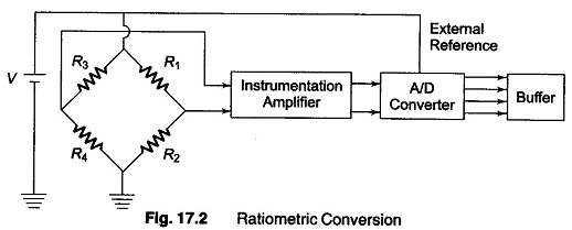
One method, as shown in Fig. 17.2, is to feed the bridge excitation voltage as an external reference voltage to the analog/digital converter, in which the conversion factor is proportional to the reference voltage. The system sensitivity is therefore independent of the excitation voltage.
Logarithm Compression (Conversion):
A logarithm compression circuit enables the measurement of a fractional change in the input as a percentage of the input magnitude rather than a percentage of a range.
For example, for an input in the rang of 100 μV to 100 mV, the output voltage may correspond to 0 for 100 μV and 3 V for 100 mV, if the logarithm conversion gain is 1% per decade.
Consider now a change of 1%, i.e. the input changes from 100 mV to 101 mV. The output of the logarithm amplifier would change by
![]()
where 1.01 is the ratio of the inputs, 101 mV/100 mV.
Since the output change is related to the ratio of the input, it is evident that the change in output is the same, i.e. 4.3 mV, whether the input changes from 10.0 mV to 10.1 mV or from 100 μV to 101 μV.
If the logarithm amplifier output is converted into digital output using a 12 bit BCD converter, the resolution of the converter would be 3 V/1000 = 3 mV for a 3 V full scale, provided the output of the logarithm amplifier is scaled properly.
With this resolution of the converter, it is possible to monitor and record changes as low as 1 μV for an input of 100 μV or 10 μV for 1 mV. If no logarithm amplifier had been used, the resolution would have been 100 μV (100 mV/1000 = 100 μV). Hence a 110 to 1 improvement is possible using a logarithm amplifier.