DC Inputs:
The, dc inputs modules commonly available will work with 5, 12, 24 and 48 volts. The DC Inputs modules allow us to connect either PNP (sourcing) or NPN (sinking) transistor type devices to them. If using a regular switch (i.e. a toggle or Push Button, etc.) then it is not important whether it is wired as NPN or as PNP. It is to be noted that most PLCs do not mix NPN and PNP devices on the same module. But when using a sensor e.g. (photo-sensor, proximity, etc.) then it is important to know its output configuration. Hence it always advisable to verify before connection whether its PNP or NPN. The difference between the two types is whether the load (in our case PLC is the load) is switched to ground or positive voltage. An NPN has the load switched to ground whereas a PNP device has the load switched to positive voltage. Figure 21.47 shows an NPN sensor (Sinking mode). In this NPN sensor one output is connected to the PLCs input and the other to the power supply ground.
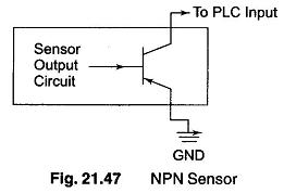
If the sensor is not powered from the same power supply as the PLC, then both the grounds should be connected.
For a PNP sensor, the load is switched to ground. On the PNP sensor, one output is connected to positive voltage and the other to the PLC’s input as shown in Fig. 21.48.
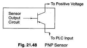
If the sensor is not powered from the same supply as the PLC, then both positive voltages (V+) should be connected together. Inside the sensor the transistor acts as a switch. The sensors internal circuit tells the output transistor to turn on when a target is present. The transistor then closes the circuit between the two connections shown above, i.e. The V + and the PLC input.
The only thing that is accessible to the user are the terminals labelled common, input 0000, input 0001, input xxxx as shown in Fig. 21.49.
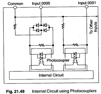
The common terminal either gets connected to V + or ground. The type of sensor used decides where the common terminal is to be connected. When using a NPN sensor this terminal is connected to V +. When using a PNP sensor this terminal is connected to zero voltage (ground).
A common switch (i.e. limit switch, push button, toggle, etc.) would be connected to DC Inputs in a similar fashion. One side of the switch would be connected directly to V + and the other end goes to the PLC input terminal. This assumes that the common terminal is connected to OV (ground). If the common terminal is connected to V+ then simply connect one end of the switch to OV (ground) and the other end to the PLC input terminal.
The photocouplers shown in Fig. 21.49 are used to isolate the PLC’s internal circuit from the DC Inputs. This eliminates the chance of any electrical noise entering the internal circuitry. They operate by connecting the electrical input signal to light and then by converting the light back to an electrical signal to be processed by the internal circuit.