Potentiometric Recorder Working Principle (Multipoint):
Potentiometric Recorder Working Principle – The thermocouple or millivolt signal is amplified by a non-inverting MOSFET, chopper stabilized, feedback amplifier. This configuration has a very high input impedance and the current passing through the signal source is a maximum of 0.5 nA (without broken sensor protection). With the use of span control, the output signal is adjusted to 5 V (nominal), for an input signal change, e.g. to full scale deflection of the pen.
The pre-amplifier output signal is then compared with a reference voltage picked off the measuring slide wire, which is energized by a stabilized power supply, and the difference amplified by a servo amplifier, whose output drives a Linear Motor. The motor carriage carries the indicating pointer pen and the sliding contact on the slide wire.
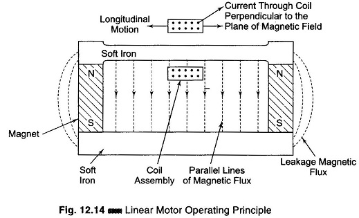
The motor itself consists of a coil assembly, travelling in a magnetic field (Fig. 12.14). The servo amplifier drives the carriage in the appropriate direction, to reduce the difference signal to zero.
An input filter circuit reduces any spurious signals picked up by the input leads. The B–E junctions of the transistor are used for overload protection.
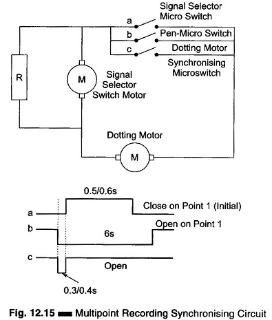
In multipoint versions of the Potentiometric Recorder Working Principle, a signal selector switch is driven by a synchronous motor. The pen changeover and dotting action are actuated by a second synchronous motor (Fig. 12.15). The pen operation is electrically synchronized to the rotation of the signal selector switch—should they get out of step, the pen motor stops at a predetermined point and restarts only when the signal selector switch has rotated to its correct alignment. The Linear Motor is muted during the signal changeover, but dotting always takes place with the system live. The standard dotting interval is 6s (Fig. 12.15). The Linear Motor consists of a coil assembly travelling in a magnetic field. The direction of the field is as shown in Fig. 12.14. The current passing through the coil produces a magnetic field which is perpendicular to the existing field and causes the carriage to move in a direction given by Fleming’s left hand rule.
Ranging Circuit:
With the indicating pointer positioned at the minimum of the scale, the output from the preamplifier should be zero. A small voltage appears across R1 and R4 due to current feeds from R2 and R3 respectively. R1 is kept less than R4 (in general, but R1 > R4 in thermocouples) and additional current is passed through R1 from RV1, so that the output can be adjusted to read zero corresponding to a zero input signal. When a signal input equivalent to full scale is given, RV3 is adjusted to make the indicating pointer read the maximum on the scale. For thermocouple inputs, the circuit remains as above. For automatic cold junction compensation, the variation in the base-emitter voltage of the transistor with respect to temperature is made use of. The resistance R7 injects current through R4. The value of R4 depends on the type of thermocouple used. Figure 12.16(a) shows a ranging circuit.
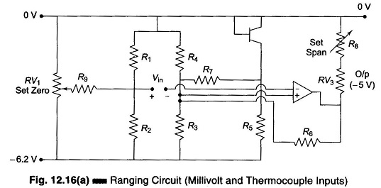
For input signals greater than 100 mV, an additional range card is used. Figure 12.16(b) shows the diagram of a resistance thermometer. For resistance thermometer input, a separate power supply gives the bridge supply as 6.2 V.
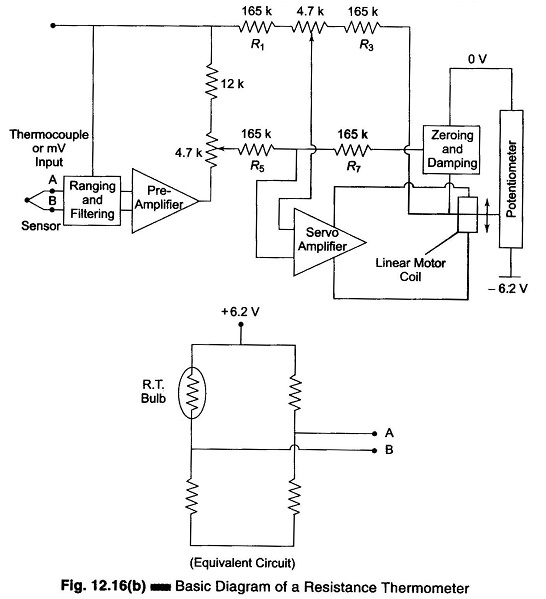
One of the arms of the bridge is a resistance bulb (the standard three wires connection of the resistance thermometer). The other three arms of the bridge are mounted on an additional range card. The bridge gives 10 mV nominal output for the range of temperatures under consideration.
Servo Amplifier Working:
The servo amplifier shown in Fig. 12.16(c) compares the output from the preamplifier with the voltage picked off the measuring slide wire. The output of the preamplifier and the voltage picked up by the slide wire obtained via an emitter follower stage are connected in a high resistance bridge circuit (R1 = R3 = R5 = R7 = 165 kΩ), the balance of which is adjusted for maximum common mode rejection by adjusting the potentiometer, RV1 (4.7 kΩ). The output is fed to the differential amplifier (consisting of a matched pair Opamps).
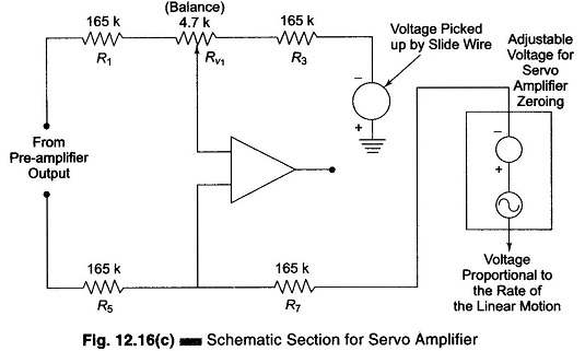
The signal voltage picked from the slide wire is also used to control the damping of the servo system. For this, signal voltage from the slide wire is fed to a differentiator circuit using an Opamp and its associated circuit and damping control.
The indicating point may be adjusted to set scale minimum, when the preamplifier output is zero. This is done by adjusting a set zero potentiometer (1 k value) coming in the damping circuit.
The output of the differential amplifier is fed to a dc amplifier (consisting of typical NPN/PNP transistor stages), which give sufficient output to drive the Linear Motor in the appropriate direction. This reduces the differential input signal to the servo amplifier to zero.
Multipoint Variation:
In multipoint recorders, each signal to be measured is connected in turn to the ranging circuit input terminals by means of a rotating selector switch, which is driven from a synchronous motor having a speed of 10 rpm via an intermittent motor. Each signal is sampled for a period of 3 or 6 seconds, depending on the switch motor fitted.
A second synchronous motor (10 rpm – 24 V ac) is mounted and fitted with cams and microswitches (Fig. 12.15).The cam at the extreme end actuates the pen lifting (and dotting) bar and initiates the pen dotting. As the stylus lifts off the paper, a pawl and ratchet system in the pen head rotates the stylus and ink well to the next point.
A synchronizing microswitch, mounted under the pen head, is operated by a pip on the stylus shaft. The contacts are open while the pen stylus is at initial point 1.
Fitted to the shaft of the dotting motor is a second cam, which operates a second microswitch in the synchronizing circuit. The contact switches are open for a period of 0.3 – 0.4s, once in each revolution of the dotting motor, which rotates once during the sampling period of each print, i.e. 6s.
The third synchronizing microswitch is operated by the projection on the side of the plastic intermittent advance gear on the same shaft of the signal switch. The contact of this microswitch closes for a period of 0.5 – 0.6s once in each revolution of the signal switch, i.e. once every 72s for a 6s sampling.
When the Potentiometric Recorder Working Principle goes out of synchronization, if the cams and pen stylus are set correctly, the dotting motor will continue operating until the stylus comes around to the initial point. At this point the pen microswitch opens, as does the dotting microswitch. The dotting motor then stops.
The signal selector switch motor operates continuously, and when the microswitch operated by this motor closes, the dotting starts again.
(Note: The closing time of the signal selector microswitch is slightly more than the open time of the dotting motor microswitch, ensuring that the dotting motor microswitch be closed again before the signal selector switch motor microswitch opens.)
Multiple Recorders (6 Point Recorders):
The controller consists of a high gain opamp in comparator configuration, with one input from the pre-amplifier and another from the set point potentiometer. The output of the comparator is connected to the Schmitt trigger via both high and low control microswitches, operated by control cams, as shown in Fig. 12.17.
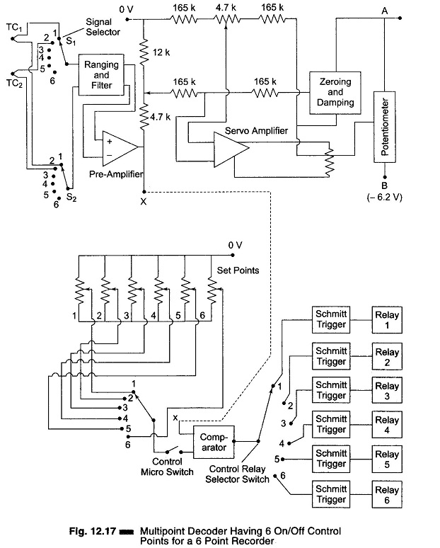
The Schmitt trigger circuit maintains the relay state after the input is disconnected, i.e. while the signal selector switches scan the other signal input. The control microswitch ensures that the relay does not change state during signal changeover, while the pre-amplifier input is open-circuit. Once the relay gets energized, it remains in that state via its own (normally open) contacts and through the Reset button.
When the Reset button is pressed, the relay gets de-energized, which again gets latched if the same condition (Vin > Vset) prevails for the same or any other channel.