Null Type Recorder:
These Null Type Recorder Working Principle of self-balancing or null conditions. When an input is given to the measuring circuit of the recorder from a sensor or transducer, it upsets the balance of the measuring circuit, producing an error voltage which operates some other device, which in turn restores the balance or brings the system to null conditions.
The magnitude of the error signal indicates the amount of movement of this balance restoring device and the direction of the movement indicates the direction of the quantity being measured.
The different types of Null Type Recorder are as follows:
- Potentiometric recorders
- Bridge recorders
- LVDT recorders (Linear Variable Differential Transformer)
1. Potentiometric Recorders:
The basic disadvantage of a galvanometer type recorder is that is has a low input impedance and a limited sensitivity. This disadvantage can be overcome by using an amplifier between the input terminals and the display or indicating instruments. This amplifier provides a high input impedance and improved sensitivity at the cost of low accuracy. To improve the accuracy of the instrument, the input signal is compared with a reference voltage using a potentiometer circuit.
The self-balancing feature is obtained with a servo motor, a motor whose speed and direction of rotation follows the output of an amplifier. In a dc system, this is simply a reversible motor, such as the type that uses a permanent magnet for its field. In the ac system, it takes the form of a two-phase motor.
Figure 12.3 is a basic circuit of a potentiometric or self-balancing recorder.
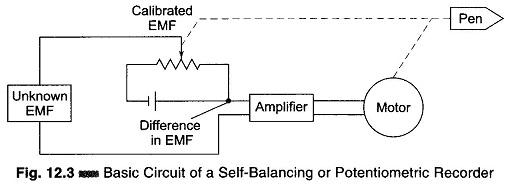
The difference between the input signal and the potentiometer voltage is the error signal. This error signal is amplified and is used to energize the field coil of a dc motor. In this circuit, instead of obtaining a balance between two opposing voltages by rotating the arm of the voltage divider, an error current is allowed to flow, either clockwise or counter clockwise, depending on which voltage is higher. This error serves as the input to the electronic detector, and the amplified error is then fed to the balancing motor. This motor is so connected that it turns in a direction that rotates the voltage divider arm (geared) to it in the direction that reduces the error. As the error becomes smaller, the motor slows down and finally stops at the point where the error is zero, thus producing the null balance.
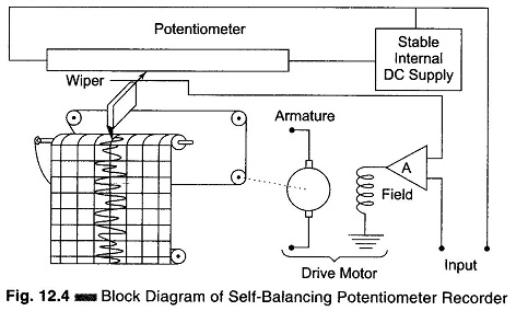
This is achieved by mechanically connecting the wiper/variable arm to the armature of the dc motor. The pen is also mechanically connected to the wiper. Hence as the wiper moves in a particular direction, the pen also moves in synchronism in the same direction, thereby recording the input waveform. The wiper comes to rest when the unknown signal voltage is balanced against the voltage of the potentiometer. This technique results in graphical recorders having a very high input impedance.
A sensitivity of 4 V/mm is attained with an error of less than ± 0.25% with a bandwidth of 0.8 Hz. A motor synchronized to power line frequency is used to drive the chart drive for most potentiometer recorders. Hence the speeds of the chart drive can be changed by the use of a gear train which uses different gear ratios. Potentiometer recorders are mostly used for the recording and control of process temperature. Figure 12.4 is the basic block diagram of a dc self balancing system. Instrument that record changes of only one measured variable are called single point recorders.
Multipoint recorders are those in which one recorder may be used for recording several inputs. These may have as many as 24 inputs, with traces displayed in six colours. The data is recorded on an 8 inch chart, at frequencies from dc to 5 kHz, models up to 36 channels are also available.
2. Bridge Type Recorders:
When a non-electrical quantity such as temperature is to be recorded, the transducer converts the temperature changes in to corresponding electrical variations.
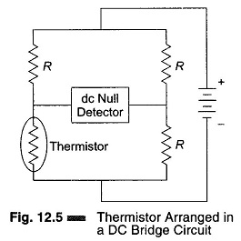
If a thermistor or resistance thermometer were used as the transducer, the changes in temperature would produce variations in the resistance of the transducer, rather than a change in voltage. In this case, the thermistor is made part of the bridge circuit, as shown in Fig. 12.5.
The resistance changes in the thermistor cause corresponding changes in the bridge output. These changes are applied to the detector. The bridge balance (null) can be restored by varying the resistance of another arm of the bridge, while recording in terms of current, voltage or temperature. Depending on the kind of voltage supplied to the bridge, the output can be chosen to be dc or ac.
3. Linear Servo Motor Recorder (LVDT):
Some temperature indicating and recording instruments incorporate a linear servo motor which dispenses with the conventional servo motor and error-prone gear train linkage and motor brushes. Improvement in reliability, speed of response, minimum resistance to movement and high accuracy are obtained with the use of linear servo motors.
The requirements of dc linear motor are as follows
- It should produce motion in straight line in response to a direct current.
- It should reverse its motion if the current polarity is reversed.
- It should be easy to control and have a low inertia.
- Its use and power requirements must be comparable with existing drive
If two permanent magnets, parallel to one another, are fixed to a bench, a small free permanent magnet placed between them will move linearly in a direction which depend on the position of the north and south poles of the fixed magnets. If a current is passed through a small coil, in place of the permanent magnet, the coil will move in a similar fashion but with the advantage that the direction of motion can be reversed by reversing the current flow.
Figure. 12.6 indicates the simple nature of motor action.
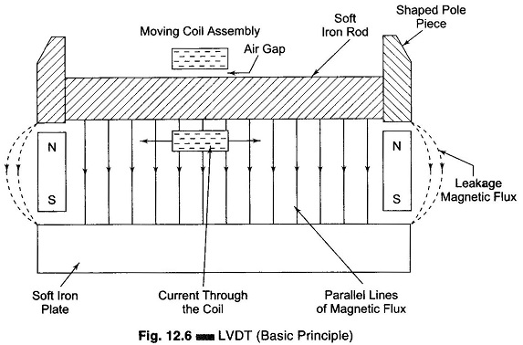
Current flow through the coil assembly generates the motor action. The force F should be sufficient to overcome the friction in the moving parts supporting the coil, the inertia of the coil assembly, plus a suitable safety factor.
The coil in the linear motor is supported by two small pulleys at the rear and the front with a spring affixed to the coil and resting on a slide wire. The pulleys are adjusted to maintain a clearance air gap around the rod. The scale pointer is part of the coil holder. This arrangement provides a direct drive for the scale pointer and slide wire contacts, enabling motion in straight line, which
- permits the use of a straight former for the slide wire, and
- enables a flat scale to be used.
Ferrodynamic (LVDT) recorders are versatile instruments used for measuring and recording process variables such as pressure, vacuum, flow, level, and angle of rotation. These instruments work on the null balance principle and are used in conjunction with suitable primary transmitters (transducers), as different transformers or induction transducers. The accuracy of these instruments is of the order of ± 0.6% of full scale division. The threshold sensitivity is about ± 0.25% of span and the response time is about 6 seconds.
Null Type Recorder Working Principle:
The Null Type Recorder Working Principle instrument comprises the following main units.
- Ferrodynamic compensating converter
- Solid state amplifier
- Balancing motor
- Linkage mechanism
- Chart drive mechanism (for recorders)
The ferrodynamic converter consists of a sturdy moving coil placed in an alternating magnet field. The magnitude and phase of the induced EMF in the moving coil depends upon the angle of rotation of the coil. A bias winding is introduced over the exciting winding, which can bodily shift the output characteristics of the ferrodynamic converter (LDVT), as shown in Fig. 12.7.
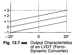
From Fig. 12.7, it can be seen that for a – 20° to + 20° rotation of the moving coil, the voltage induced varies by 2 V. By having a bias winding, it is possible to obtain signals of range – 1 V to + 1 V, 0 V to + 2 V, and + 1 V to + 3 V.
The output from the primary transmitter (LVDT) is connected in phase opposition to the output from the ferrodynamic compensating converter. The resultant difference voltage, is amplified by the solid state electronic amplifier which drives the balancing motor. Through mechanical linkage, the balancing motor in turn positions the moving coil of the converter in such a way that the unbalance voltage becomes zero. The motor’s output through some mechanical linkage and cam mechanism is also fed to the pointer and the pen, which moves on a scale calibrated in terms of the measured variable.
Chart Drive Mechanism:
The usefulness of a recording instrument depends upon
- The selection of the proper chart speed, and
- The selection of the suitable drive element.
The selection of chart speeds is an important factor for separating the records of specific deviation. A drive element should be a positive drive, it should require minimum maintenance and be able to run under certain extreme ambient conditions.