Servo Type Voltage Regulator Working Principle:
The main features of a servo type voltage regulator using an amplidyne is depicted in Fig. 19.8. The servo type voltage regulator system comprises of a constant voltage main exciter driven from the alternator shaft and an auxiliary exciter whose field is controlled by amplidyne. Both the auxiliary exciter and amplidyne are driven by a dc motor coupled to both the machines. The dc motor is supplied from the main exciter. The main exciter has a saturated magnetic circuit and hence has a roughly constant output voltage. The armatures of main and auxiliary exciters are connected in series and this series combination excites the field winding of the alternator.
Thus, the auxiliary exciter controls the excitation current of the alternator by a buck-boost action.
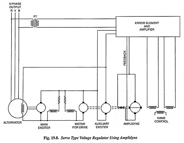
The potential transformer (PT) provides a signal, proportional to the alternator output voltage, to a voltage sensitive bridge one arm of which consists of saturated diode. Any deviation in the output voltage of the alternator produces a corresponding change in the output of an electronic amplifier. The amplifier output feeds the amplidyne control field. The amplidyne output alters the auxiliary exciter field. Thus, the auxiliary and the main exciter in series adjust the excitation current of the alternator, according to the load needs, to maintain its output voltage constant within the specified limits.
The several time lags in the circuit needs negative feedback for stabilization of the system response. Feedback is also given from the amplifier circuits to the amplidyne as well as the auxiliary exciter.