Vacuum Triode, Construction and Working:
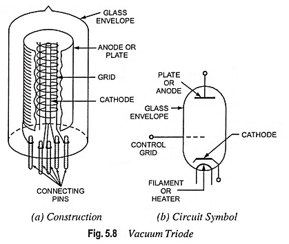
Construction of Vacuum Triode – The construction and the schematic symbol used for a vacuum triode are illustrated in Fig. 5.8. It, as the name suggests, consists of three electrodes namely, cathode (filament type or indirectly heated oxide coated type), anode and control grid (or simply grid). The cathode is located at the centre of the tube and is surrounded by the control grid which in turn is surrounded by the anode (or plate). The grid is nearer to the cathode than to the plate. The cathode and anode are normally of the same type of construction as for a vacuum diode. The control grid has a mesh structure so that the electrons emitted by the cathode can pass through it. Grid structures are of several types such as circular helix, flattened or elliptical helixes, ladders etc. Metals used for grids are nichrome, molybdenum, iron, nickel, tungsten, tantalum and various alloys. The whole assembly of heater filament, cathode, grid and plate is placed inside an evacuated glass envelope. The connections for grid, plate, cathode and heater filament are usually brought out at the base of the tube. Sometimes the grid, or the plate connections may he brought out to a pin on the top of the glass envelope. The plate is provided with cooling fins so as to increase the heat dissipation capacity of the tube. Triode tubes differ widely in size and electrode spacings depending on their power ratings and on the purposes for which they are intended to be used. The primary function of the grid is to serve as an electrostatic screen and to partially shield the cathode from the electrostatic field of the anode or plate.
Operation of Vacuum Triode:
When the cathode is heated it starts emitting electrons by thermionic emission. Since the plate is always positive w.r.t. cathode, it attracts the electrons from the space charge resulting in flow of current from cathode to plate through external circuit. When the grid is at zero potential w.r.t. cathode, the presence of grid does not affect the electric field between anode and cathode and the triode behaves like a diode. When the grid is placed at some positive potential w.r.t. cathode, it tends to neutralize the space charge in the region of the cathode, thus enables the plate to maintain a large current flow. When the grid is placed at some negative potential w.r.t. cathode, it will act in the same manner as the space charge and will repel the negative electrons towards the cathode and hence will reduce the plate current. If the grid is made sufficiently negative, it will stop completely the flow of electrons. Thus, the plate current can be increased, reduced or switched off completely by varying the potential of the grid. The value of grid voltage, which makes the plate current zero, is known as cut-off grid voltage. The value of cut-off grid voltage depends upon the value of plate voltage and characteristic of the tube. The more the value of plate voltage, the more negative is the value of the cut-off grid voltage.
From the above discussions it is obvious that the grid regulates the flow of electrons inside the plate circuit and thus controls the plate current. Owing to the controlling property the grid is called the control grid. Though the plate current can also be controlled by varying plate voltage as in the case of a diode but control grid, being nearer to the cathode than the plate, controls the plate current more effectively—a change of one volt in grid potential will produce many times the change in plate current that a change of one volt in the plate voltage will produce. It is the action of grid in an electron tube that enables it to act as an amplifier of small voltages or currents.
It should be noted that triode tubes are usually designed for normal operation with a negative bias so that they may not draw current and consume power. Such tubes cannot be operated with zero or positive bias without damage to the tube owing to excessive plate current.
Operating Characteristics:
In the design of the electronic circuits using Vacuum Triode it is necessary to know the behavior of the tube under different grid and plate voltages. The relationships between plate current, plate voltage and grid voltage can be conveniently given by performance curves known as characteristics. If the characteristics are drawn without load we obtain static characteristics. The characteristics obtained under actual operating conditions with a signal voltage applied to the grid and a load resistance inserted in the plate circuit to extract power from the tube, are known as dynamic characteristics.
Static Characteristics. These are of three types namely
- plate characteristic,
- mutual or transfer characteristic and
- constant current or amplification characteristic.
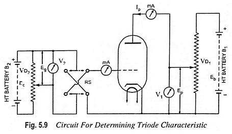
The circuit diagram for determining the static characteristics of a Vacuum Triode is shown in Fig. 5.9. The plate is connected to the +ve terminal of battery B1 through a voltage divider VD1. By adjusting the voltage divider VD1 any desired potential can be applied to the plate. Similarly the battery B2 maintains the potential of the grid at any desired value, positive or negative, through voltage divider VD2 with the help of reversing switch RS. A milliammeter is connected in the plate circuit to measure plate current and voltmeters V1 and V2 are connected in the circuit to measure plate and grid voltages respectively.
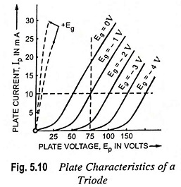
1. Plate Characteristic (Plate Current—Plate Voltage Characteristic). The curve drawn between plate current and plate voltage, keeping grid potential constant, is known as plate characteristic. The plate characteristic can be obtained by keeping grid potential Eg constant at a particular value, varying the plate voltage in steps, noting the corresponding plate current and plotting the results so obtained. The process is repeated at different grid potentials. The plate characteristics for a typical Vacuum Triode are shown in Fig. 5.10. From Fig. 5.10, it is obvious that the curves have a similar shape, being curved in the lower portion near plate current cut-off and fairly linear in upper portions. The curvature at the low plate current is due to space charge. At higher plate currents there will be a bend again because of saturation but this bend has not been shown in the figure because oxide emitters are avoided to be operated at saturated condition. The portion of the characteristic between upper and lower bends is most useful for the purpose of amplification.
2. Transfer or Grid or Mutual Characteristic. Transfer or mutual or grid characteristic is the curve drawn between plate current and grid voltage, the plate voltage being kept constant. The transfer characteristic can be obtained by keeping plate voltage Ep constant at a particular value varying the grid potential, noting the corresponding plate currents and plotting the results so obtained. The process is repeated at different plate voltages, The transfer characteristics for a typical triode are shown in Fig. 5.11.
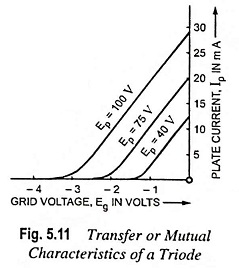
When the grid is positive, it helps the plate to attract the electrons hence plate current is increased. When the grid is negative with respect to cathode it retards the action of plate and hence plate current is reduced. It is to be noted that each curve intersects the grid voltage axis at a specific point that indicates the value of the negative grid voltage required to make the plate current zero at the particular value of applied voltage to plate. This is also called cut-off bias. As the plate voltage is increased, it may be seen that the negative bias required to make the plate current zero also increases.
The transfer characteristics are of the same form as the plate characteristics. Triodes are almost always operated in the linear portion of their characteristics and rarely in the curved portions. This is because increase in grid voltage does not result in proportional increase of the plate current in the curved portions of the characteristics.
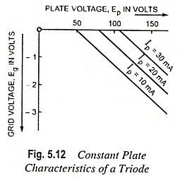
3. Constant Current or Amplification Characteristic. The curve drawn between plate voltage and grid voltage, plate current being kept constant, is known as constant plate current characteristic. For obtaining data for this characteristic the circuit diagram shown in Fig. 5.9 is used. First of all the plate is given a suitable high potential and then grid voltage is changed until the highest plate current for which it is desired to obtain the characteristic is obtained. Now plate potential is reduced in steps and at each step the grid voltage is readjusted so that the same plate current is obtained. This is repeated with different plate currents and curves are plotted, as shown in Fig. 5.12.
Vacuum Tube Coefficients:
The slope of a static characteristic at its usual operating point or at a predetermined point on the characteristic is known as the tube coefficient or tube factor. The three most important tube coefficients used for determining the performance of vacuum tubes are, the amplification factor, the plate resistance and the transconductance. These tube coefficients can be determined from the three families of characteristic curves, described above, by noting the slope of the curve.
Amplification Factor. It is a measure of the relative effectiveness of the control grid in overcoming the electrostatic field produced by the plate. Numerically, it expresses how much more effective the grid voltage is in producing an electrostatic field at the cathode surface than the field set up by the plate voltage. Its value depends to a large extent on the spacing between the grid and plate. Its value can be determined by changing the plate voltage in the opposite direction by an amount just sufficient to restore the previous plate current value. The ratio of change in plate voltage to the change in grid voltage, so that they may neutralize each other’s effects on the plate current, is known as amplification factor and is denoted by Greek letter μ.
Mathematically amplification factor,
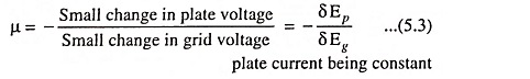
The -ve sign indicates that the changes in two voltages are oppositely directed.
Obviously, amplification factor, μ is nothing but the slope of the constant plate current characteristic.
Plate Resistance. When a current flows through a tube from plate to cathode, there is a voltage drop across the tube and electrical energy is converted into heat at the rate of Ep Ip watts where Ep and Ip are plate voltage and plate current respectively.
This is exactly what happens when a current is made to flow through a resistance, so it is convenient to regard this path through the tube as having resistance, even though the physical nature of that resistance is rather different from the resistance of a piece of wire. In practice, we are interested mainly in the resistance offered by the tube to the ac component of the plate current, and therefore plate resistance is defined as the ratio of change in plate voltage to the change in plate current, grid voltage remaining the same. It is denoted by rp and measured in ohms.
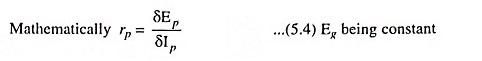
The coefficient rp is often called as dynamic or incremental plate resistance. The coefficient rp is also obtained by taking reciprocal of the slope of the plate characteristic curve.
Transconductance. Transconductance, sometimes called mutual conductance, of a tube is defined as the ratio of a small change in plate current to the small change in grid voltage, the plate voltage remaining the same. It is denoted by gm and measured in micro-mhos or micro-siemens.
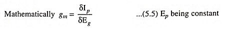
As transconductance, gm is the ratio of current to voltage, therefore, it should be expressed in mhos (siemens). Since vacuum tubes are low current devices, the transconductance will be a fraction of 1 mho (siemen) so it is more convenient to express gm in micro mhos (micro siemens).
The transconductance is the most important tube coefficient as it reveals the effectiveness of the control grid in securing changes in the plate current and, hence, in the signal output of the tube. Its value can be easily determined from the slope of mutual characteristic of the tube.
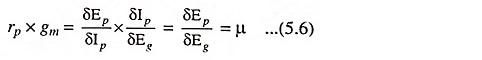
Relationship Between Three Tube Coefficients. The three tube coefficients are interrelated, in accordance with their definition, as is easily shown by multiplying the relation defining the plate resistance and transconductance.
Dynamic Characteristics:
All the three types of static characteristics discussed above, provide relationship between plate voltage Ep, plate current Ip and grid voltage Eg and each characteristic provides the relationship between two quantities while the third is kept constant. For example the mutual characteristic provides relationship between plate current and grid voltage while plate voltage is kept constant. When there is no load resistance in the plate circuit, there will be no voltage drop in the plate circuit, hence plate voltage would remain the same irrespective of the magnitude of plate current. Hence matter is simple. But in actual operating conditions, there is always a load in the plate circuit. Let there be a load resistance RL in the plate circuit, as shown in Fig. 5.13. Now voltage applied to the plate is given by the expression.
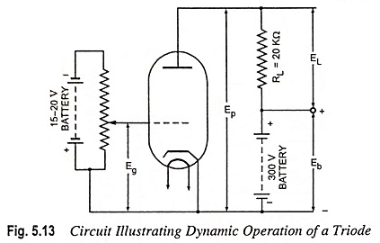
Ep = Eb – Ip RL where Eb is the terminal voltage of ht battery.
Hence in practice with the change in grid voltage Eg, plate current Ip changes which in turn changes the plate voltage and change in plate voltage affects the change in plate current.
In short the curve drawn between grid voltage Eg and plate current Ip with no load in the plate circuit is known as static characteristic since plate voltage Ep remains constant. The curve drawn between grid voltage Eg and plate current Ip with a load in the plate circuit is known as dynamic characteristic since plate voltage Ep is variable or dynamic.
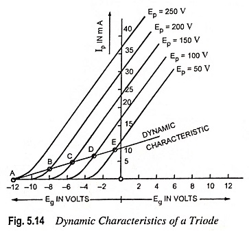
Dynamic characteristics are usually drawn over the static transfer or mutual characteristics. Let the dynamic characteristics be drawn for plate voltage of 250, 200, 150, 100 and 50 volts, load resistance be of 20 kΩ and terminal voltage of ht battery be 250 volts.
First of all draw mutual characteristics at plate voltages of 250, 200, 150, 100 and 50 V respectively, as explained above.
1. When plate voltage Ep is of 250 V,
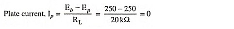
Hence point A corresponding to plate voltage of 250 V and zero plate current and lying on dynamic characteristic is obtained.
2. When plate voltage Ep is of 200 V,
Hence point B corresponding to plate voltage of 200 V and plate current of 2.5 m A lying on dynamic characteristic is obtained.
3. When plate voltage Ep is of 150 volts, Plate current,

Hence point C is obtained on the dynamic characteristic.
4. When plate voltage Ep is of 100 volts, Plate current,
![]()
Hence point D is obtained on the dynamic characteristic.
5. When plate voltage Ep is of 50 volts, Plate current,

Hence point E is obtained on the dynamic characteristic.
Curve drawn passing through points A, B, C, D and E provides us the dynamic characteristic for a load resistance of 20 kΩ.
Similarly dynamic characteristic can be drawn for other loads. It can be seen from the curves that the dynamic characteristics are less steep than the static characteristics.
Dynamic characteristics are nearly straight, except for the curve portion near the cut-off, which means that harmonic distortion is less. With the increase in load resistance RL, the curve becomes more and more straight (flat) which indicates that harmonic distortion is reduced with the increase in load resistance RL.
Load Line:
The characteristic curve showing the variations of the plate current and plate voltage under actual operating conditions of a tube is known as load line for a given load resistance. Load lines are drawn on the static plate characteristics, as shown in Fig. 5.15. It can be seen that load line conveys that with the increase in plate current, plate voltage must decrease and vice versa.
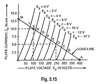
At point A i.e. when plate current Ip is zero plate voltage Ep becomes equal to battery voltage, let it be 400 V, because grid voltage, Eg = Cut-off bias voltage.
At point L when grid voltage is zero, plate current has definite value and thus plate voltage is always less than battery voltage. Thus difference of the above two voltages is equal to the potential drop across the load resistance. Other points between A and L shall correspond to other grid voltages. Slope of the load line depends upon the value of load resistance.
Let the battery voltage be 400 volts and load resistance be of 30 kΩ.
When plate current Ip = 0, plate voltage = 400 V, hence giving point A on the load line.
When plate current Ip = 10 mA.
Plate voltage, Ep = Eb -Ip RL = 400 – 10 x 30 = 100 volts, hence giving point K on the load line.
Now the load line can be drawn by joining points A and K and extending it to meet Y-axis at point M. The point M indicates that when plate current is 13.33 mA, plate voltage is zero.
Nov for any value of grid voltage Eg we can find the corresponding values of plate voltage and plate current from the co-ordinates of the intersection of load line and the curve for grid voltage Eg. Thus when grid voltage is -10 volts the plate current is 5 milli-amperes and the plate voltage is 250 volts.
Triode as a Rectifier:
As already discussed, Vacuum Triode is a diode with its effective space charge controlled through the control grid. The electrons emitted by the cathode can be attracted by the anode only when the anode is positive w.r.t. cathode. Also the anode is not an electron emitter so the conduction can take place only when anode is positive w.r.t. cathode and only in one direction. Thus a triode can be employed as a rectifier but it is not. The reason is that triodes are usually designed for very small value of plate current and cannot be employed for current ranges for which diode rectifiers are usually designed. However, for low capacities, triode can be used for rectification. For this purpose a separate supply for grid may or may not be connected. In some cases grid may be externally connected to cathode for bringing it to the cathode potential. This is as effective as the absence of space charge in the triode.
Triode as an Amplifier:
A device, which amplifies or increases in magnitude any current, voltage or power applied to its input side is known as an amplifier. The amplification of weak alternating signal voltage without change of waveform is an important application of a Vacuum Triode. Such a signal voltage may be obtained from a radio receiving aerial, a gramophone pick up or microphone.
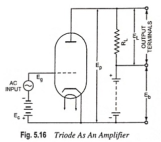
Figure 5.16 represents the circuit diagram of a Vacuum Triode as an amplifier capable of amplifying the signal voltage of peak value Eg. The battery of voltage Ec, Ec being greater than peak signal voltage, Eg, is inserted in the grid circuit to maintain the grid at a potential negative to that of cathode at all times regardless of the polarity of signal source. Ec is known as the grid bias voltage of a triode as an amplifier. A straight portion ABC of a dynamic mutual characteristic of a tube is considered, as shown in Fig. 5.17.
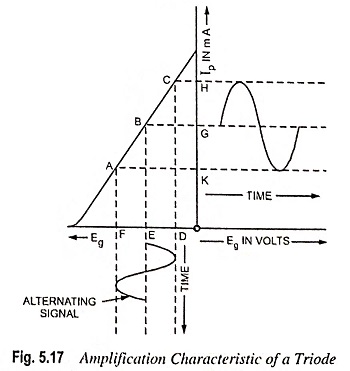
In the Fig. 5.17 OE represents the grid bias voltage Ec and the plate current corresponding to grid voltage Ec is that represented by OG. Due to input alternating signal in the grid circuit, the grid voltage varies between (Ec + Eg) and (Ec – Eg) represented by OF and OD. The corresponding plate current varies between OH and OK. From Fig. 5.17, it is evident that the variation of the current in the plate circuit, hence in plate voltage, is greater and depends upon the slope of dynamic characteristic. Larger amplification in voltage is obtained when the steepest part of the curve is obtained.
Voltage Amplification. Let RL = load resistance in plate circuit; rp = resistance of tube; μ = amplification factor; Eg = grid voltage; Ep = plate voltage; and Ip = plate current.
Change in potential across load is given by δEL = δ IpRL
By definition

where δEp is the total change in plate voltage and is equal to Ip (RL +rp)

Hence actual voltage amplification.
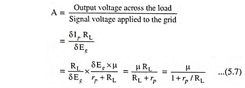
If RL → ∞, then A = μ
Remarks :
1. In order to obtain amplification free of distortion the straight line portion of the dynamic characteristic should be used because the nature of variation of plate current is exactly the same as that of variation in grid voltage.
2. The grid should be given high negative potential with respect to cathode for stopping the current in grid circuit.
Triode as an Oscillator:
An electronic device which converts unidirectional current drawn from a dc source of supply into alternating current of high frequency, is called the oscillator. The function of oscillator is reverse of that of a rectifier and therefore, sometimes called the inverter.
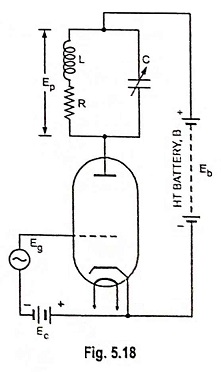
Principle of Operation of Vacuum Triode as an Oscillator. Suppose that an alternating voltage Eg is applied to the grid of a triode amplifier, as shown in Fig. 5.18, the frequency being equal to the parallel resonant frequency of the tuned plate circuit. At this frequency the tuned circuit has a total impedance which is resistive and has a magnitude of L/CR being known as dynamic resistance of the circuit. Then an alternating voltage Ep will act across the tuned circuit and generally Ep is much greater than Eg. If Eg is not large enough to cause grid current, the power required in the grid circuit is negligible. But there is appreciable power in the plate circuit derived from the plate circuit battery B and converted into ac power by the action of Eg on the plate current. It would then seem possible to supply the grid input Eg from the plate circuit and in fact it can be done in many ways. The requirement is that the phase of the applied voltage to the grid is proper.
Essential Parts of Triode Oscillators. Every oscillator consists of the following parts:
- An oscillatory (resonant) L-C circuit to determine the frequency of oscillations, being equal to 1/2π√LC. Such a circuit is known as a tank circuit.
- A dc source to replenish losses in the tank circuit.
- A feedback circuit for supplying energy from the source in the right phase (timing) to aid the oscillations i.e. regenerative feedback.
For sustained oscillations it is essential that the tube has sufficient amplification (μ) and a sufficient amount of energy is fed back to the tank to overcome all circuit losses.
Limitations of Vacuum Triode:
The Vacuum Triode, though finds wide applications as amplifiers, detectors and oscillators at audio or radio frequencies, but has two serious drawbacks namely interelectrode capacitance and low amplification.
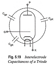
Interelectrode Capacitance. It is well known that capacitance exists between two metal surfaces separated by a di-electric. In a Vacuum Triode, electrostatic fields exist between the plate and grid, grid and cathode, and plate and cathode. Thus the capacitance exists between these electrodes, vacuum being treated as the dielectric. The capacitances between plate and grid, grid and cathode and plate and cathode are known as interelectrode capacitances and are denoted Cgp, Cgk and Cpk respectively. These interelectrode capacitances are shown in Fig. 5.19. All these capacitances are stray or parasatic capacitances, because they are not deliberately introduced.
The value of capacitance depends upon the distance between the electrodes and their nature of construction. The values of interelectrode capacitances are quite small (ranging from 2 to 12 pF) and so the reactances are quite high at low frequencies. Thus the effects of interelectrode capacitances at low frequencies are quite negligible, and the Vacuum Triode operates as an excellent amplifier for low frequency signals.
But at high frequencies, the interelectrode capacitances introduce serious complications in the operation of a Vacuum Triode as an amplifier. The capacitances Cgk and Cpk are not very important and they can generally be incorporated into the associated circuitry. However, the interelectrode capacitance between plate and grid, Cgp at high frequencies becomes of utmost importance and most undesirable as it provides a path linking the plate and grid circuits. At high frequencies, the value of reactance Xcgp is quite low and so a part of the plate (output) signal may be fed back to the grid (input) circuit through Cgp. The capacitive feedback is negative and not only reduces the amplification but also may cause instability and oscillations in the triode amplifier circuit. It is due to this reason that triodes are generally employed for amplifying signals of frequencies not exceeding 20 kHz.
Low Amplification. The amplification factor μ of a triode is usually small (not exceeding 100). This is due to insufficient shielding between plate and cathode. The control grid which is to provide the necessary shielding allows a part of electric field to penetrate through it. The result is that the plate current depends partly on grid voltage and partly on the plate voltage. If control grid is made more effective in controlling the plate current by having a control grid with very finely spaced spiral, the electrons will encounter difficulty in passing through the grid openings and so the plate current will be reduced. Thus there is a limit of effectiveness that the control grid can be made to have. This is the reason that the amplification factor of a Vacuum Triode is low.
The above drawbacks are overcome by making use of multi-electrode tubes, which will be described in the following articles, The operation of multi-electrode tubes is more efficient, convenient and stable than a triode in case such as radio-frequency operations.