Planar Triode Construction:
Planar Triode Construction – A short transit time is essential if grid loss and noise are to be minimized, as is the reduction of internal capacitances and inductances. Also, since coaxial resonant lines and cavities are used as tuned circuits at these frequencies, tubes should be built so as to connect to such lines or resonators directly.
To reduce transit time, the various electrodes are brought as close to each other as possible, while it is ensured that they cannot touch, even when a tube is jarred. Increased anode voltage will also help to reduce the transit time, and so will increased anode current, for rather complex reasons. Interelectrode capacitance is proportional to the electrode area and inversely proportional to the distance between electrodes. Thus, if both are reduced by the same so-called scaling factor, the nearness of electrodes will not increase the capacitance between them. Finally, lead inductances may be reduced by having leads in the form of rings.
The reduced area of the electrodes will undoubtedly reduce the maximum allowable dissipation; it thus follows that as operating frequency is raised, less output power is available from tubes (and any other devices). The frequency range is extended by the use of improved constructions and forced cooling, so that external anodes with cooling fins are generally used.
As a result, tubes are capable of continuous powers from over 100 W at 1 GHz to about 25 mW at 10 GHz. The pulsed powers (duty cycle 0.1 percent) over that range are 15 kW to 350 W. In the middle of this range, at 3 GHz, typical gains are 10 to 20 dB, and efficiencies 30 percent CW to 55 percent pulsed.
Of the various tubes that have been used for microwaves, only the disk-seal triode is still in use, because it is capable of high powers the figures quoted above are for this type. It comes in various versions, all of which have in common extreme closeness of electrodes, high voltages, small electrode areas but large volumes (for dissipation), ceramic bodies, and electrodes in the form of disks to reduce inductance and facilitate connection to resonant lines or cavities.
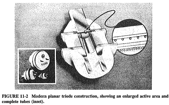
One type of this Planar Triode Construction is shown in Figure 11-2. The enlargement of the active region shows why this is often called a Parallel-plane tube. It will be seen that the cathode and plate have fairly large volumes but low active areas. Because these areas are plane, a planar grid is mounted between them, with very close spacing as indicated. The close spacing is possible because all the electrodes are solid and firmly attached to the body of the tube. They are thus unlikely to touch each other if the tube is subjected to mechanical vibration or shock. The electrode connections are cylinders or rings; they are often made of copper-tungsten. Together with the ceramic body, this permits high operating temperatures and large power dissipation.
The connections to the electrodes are designed for direct termination to coaxial lines. A typical tube of the family shown may have an overall height of 24 mm, a diameter of 19 mm, and a pulsed power output of 2 kW at 4.1 GHz. A somewhat different version of the Planar Triode Construction is the lighthouse tube, which features radiating fins for the anode and is thus capable of higher powers.
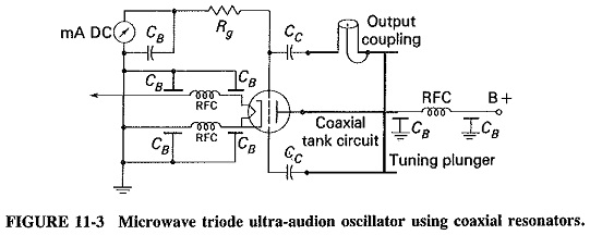
Amplifiers at UHF and above use the grounded-grid configuration, and the oscillators use the ultra-audion version of the Colpitts, as shown in Figure 11-3. RF chokes and feed-through capacitors are used for isolation and decoupling, while transmission lines are the tuned circuits.