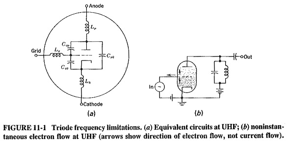
Triode Equivalent Circuit:
Triode Equivalent Circuit – As frequency is raised, vacuum tubes suffer from two general kinds of problems. The first is concerned with interelectrode capacitances and inductances, and the second is caused by the finite time that electrons take to travel from one electrode to another in a tube. Noise tends to increase with frequency, and thus microwave tubes are invariably triodes, these being the least noisy tubes.
“Standard” limitations:
At UHF and above, interelectrode capacitances cannot be ignored, nor can series electrode inductances due to internal connecting leads. Figure 11-1a shows the Triode Equivalent Circuit. However, if this is an ordinary RF tube, the capacitances will all be of the order of 2 pF, and the inductances are typically 0.02 μH. At 500 MHz, input and output shunt impedances will thus be of the order of 160 Ω (capacitive), and series impedance are 60 Ω (inductive). The maximum possible inductances of external tuned circuits will be severely limited, as will their Q. Neither short circuits nor connections directly to electrodes will be possible even internal self-oscillation will occur. Trying to use such tubes would be like employing AF devices each of whose electrodes has a 20-mH coil connected to it, as well as a 2-μF bypass capacitor! Needless to say, the difficulties increase with frequency, and would be 10 times as bad at 5 GHz.
The skin effect causes very significant increases in series resistance and inductance at UHF, unless tubes have been designed to minimize the effect. Also, dielectric losses increase with frequency. Accordingly, unless tubes and their bases are made of the lowest-loss dielectrics, efficiencies are reduced so much that proper amplification cannot be provided.
Transit time effects:
Transit time effects, it should be noted, apply not only to tubes but also to transistors and any other devices which depend on short times between electrodes.
At low frequencies, it is possible to assume that electrons leave the cathode and arrive at the anode of a tube instantaneously. This can most certainly not be assumed at microwave frequencies. That is to say, the transit time becomes an appreciable fraction of the RF cycle. Several awkward effects result from this situation. One of them is that the grid and anode signals are no longer 180° out of phase, thus causing design problems, especially with feedback in oscillators. Another important effect possibly the most important is that the grid begins to take power from the driving source. The power is absorbed (and dissipated) even when the grid is negatively biased.
Figure 11-1b shows the electron distribution in a Triode Equivalent Circuit at an instant of time when the voltage on the grid is becoming less negative. The tube is biased and driven so that the grid always remains negative, but its instantaneous voltage of course varies with the RF drive. It is seen that there are more electrons on the cathode side of the grid than on the plate side, The reason is that the electrons about to arrive at the anode left the cathode when the grid voltage was quite negative, and thus the electron flow rate was low. The electrons now in the cathode-grid space left the cathode subsequently, when the grid was less negative, and consequently there are more of them. This occurs because the RF cycle is short enough for the grid voltage to change appreciably during the time it takes electrons to travel from the cathode to the plate.
If Kirchhoff’s current law is now applied to the grid, we find more electrons internally arriving than leaving. Hence electrons must flow out of the grid; i.e., current must flow into it. Note that this occurs when the grid is becoming more positive (or less negative, which is the same thing), and that this constitutes a positive conductance. During the opposite part of the cycle, the reverse will apply, and current will flow out of the grid. Thus, to the driving source, the tube appears to have a finite conductance connected across its input, and as the frequency is increased, so is the conductance. Consequently, the driving source becomes so loaded that ultimately overall gain drops below unity, at which point the device has become nothing more than a fancy attenuator. This effect is proportional to the square of the operating frequency.
Finally, the increased input conductance increases input noise. Long before 1 GHz is reached, ordinary RF tubes have a noise figure very much in excess of 25 dB. As a conclusion, it is true to say that when any tube (or transistor) eventually fails at high frequencies, transit time is the “killer,” in one way or another.
