Crystal Equivalent Circuit:
Crystal Equivalent Circuit – The output frequency of oscillator circuits is normally not as stable as required for a great many applications. The component values all have tolerances, so that the actual oscillating frequency may easily be 10% higher or lower than the desired frequency. However, by making a capacitor or resistor partially adjustable, the frequency of most oscillator circuits can be set fairly precisely. Such adjustments may not be convenient in production circuits.
A further problem is that component values vary with the changes in temperature, and this causes changes in oscillating frequency. The component temperature changes might be due to variations in the ambient temperature, or the result of component power dissipation. A well-designed circuit (of any type) normally uses as little power as possible to avoid component heating and to reduce the power supply load. Oscillator frequency stability can be dramatically improved by the use of piezoelectric crystals.
Piezo Electric Crystals:
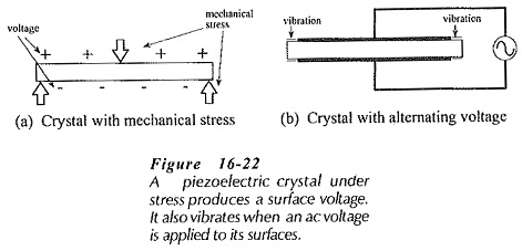
If a mechanical stress is applied to a wafer of quartz crystal, a voltage proportional to the pressure appears at the surfaces of the crystal, [see Fig. 16-22(a)]. Also, the crystal vibrates, or resonates, when an alternating voltage with the natural resonance frequency of the crystal is applied to its surfaces, [Fig. 16-22(b)]. All materials with this property are termed piezoelectric. Because the crystal resonance frequency is extremely stable, piezoelectric crystals are used to stabilize the frequency of oscillators.
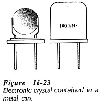
Quartz crystals for electronics applications are cut from the natural material in several different shapes. The crystals are ground to precise dimensions, and silver or gold electrodes are plated on opposite sides for electrical connections. The crystal is usually mounted inside a vacuum-sealed glass envelope or in a hermetically-scaled metal can. Figure 16-23 shows a typical crystal contained in a metal can enclosure. Crystals are also available in surface-mount and other types of enclosures.
Crystals Equivalent Circuit:
The electrical Crystal Equivalent Circuit is shown in Fig. 16-24(a). The crystal behaves as a series RLC circuit (Rs, Ls, Cs) in parallel with the capacitance of the connecting terminals (Cp). The series RLC components are referred to as the motional resistance (Rs), the motional inductance (Ls), and the motional capacitance (Cs), because they represent the piezoelectric performance of the crystal.
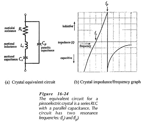
Cp is sometimes referred to as a parasitic capacitance. Because of the presence of Cp, the crystal has a parallel resonance frequency (fp) when Cp resonates with the series circuit reactance, as well as a series resonance frequency (fs), when Ls and Cs resonate. At series resonance the device impedance is reduced to Rs, and at parallel resonance the impedance is very high.
Figure 16-24(b) shows that, like all RLC circuits, the impedance of the crystal equivalent circuit is capacitive below the series resonance frequency and inductive above fs. At frequencies greater than fs, the series RLC circuit becomes inductive until it resonates with the parallel capacitance at fp. The impedance of the complete circuit then becomes capacitive (with increasing frequency) as the reactance of Cp is reduced. The two resonance frequencies (fs and fp) are very close together.
A measure of the quality of a resonance circuit Is the ratio of reactance to resistance, termed the Q factor. Because the resistive component of the crystal equivalent circuit is relatively small, crystals have very large Q factors. Crystal Q factors range approximately from 2000 to 100 000, compared to a maximum of about 400 for an actual LC circuit. Resonance frequencies of available crystals are typically 10 kHz to 200 MHz.
When a series LRC circuit is operating at its resonance frequency the inductive and capacitive reactances cancel each other, and the power supplied is dissipated in the resistance. If the power dissipation increases the temperature of a crystal, the resonance frequency can drift by a small amount. Most crystals maintain their frequency to within a few cycles of the resonance frequency at 25°C. For greater frequency stability, crystals are sometimes enclosed in an insulated, thermostatically controlled, crystal oven.
Crystals Control of Oscillators:
The frequency of an oscillator may be stabilized by using a crystal operating at either its series or parallel resonance frequency. The circuit is then usually referred to as a crystal oscillator.
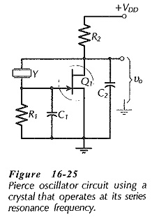
In many circuits the crystal is connected in series with the feedback network. The crystal offers a low impedance at its series resonance and a high impedance at all other frequencies, so that oscillation occur only at the crystal series resonance frequency. The Pierce oscillator in Fig. 16-25 would appear to be such a circuit, however, it actually operates as a Colpitts oscillator. Capacitors C1 and C2 are present at the input and output of the inverting amplifier [compare to Fig. 16-6(a)]. A Colpitts oscillator also has an inductor connected between the amplifier input and output. In Fig. 16-25 the crystal behaves as an inductance by operating at a frequency slightly above fs, (see Fig. 16-24).
The circuit in Fig. 16-25 is often used as a square wave generator or clock oscillator for digital circuit applications. In this situation, the amplifier gain is made as large as possible, so that Q1 is driven between saturation and cutoff to produce a square wave output.
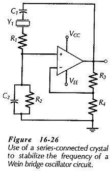
Figure 16-26 shows one method of modifying a Wein Bridge oscillator for frequency stabilization. The crystal is connected in series with C1 and R1, and in this situation it offers a low resistance at its series resonance frequency (fs), and a relatively high impedance at all other frequencies. Feedback voltage from the output via C1 and R1 is severely attenuated at all frequencies except fs, so the circuit can oscillate only at fs.
A crystal-controlled Wein bridge oscillator circuit is first designed without the crystal. A crystal is selected with fs equal to the desired frequency. Then, the circuit is modified by subtracting the crystal series resonance resistance (Rs) from the calculated value of the series resistor, (R1 in Fig. 16-26). Alternatively, circuit design could start by selection of a crystal R1 is then made larger than Rs, and R2 = (R1 + Rs). C1 and C2 are calculated from fs and R2.
The crystal power dissipation must be kept below the specified maximum. Too much power can overheat the crystal and cause drift in the resonance frequency. Also, like other devices, too much power dissipation can destroy a crystal. Typical maximum crystal drive powers are 1 mW to 10 mW, but manufacturers usually recommend operating at 1/10 of the specified maximum.
The dc insulation resistance of crystals ranges from 100 MΩ to 500 MΩ. This allows them to be directly connected into a circuit without the need for coupling capacitors. Care must be taken in any crystal oscillator circuit to ensure that the crystal does not interrupt the flow of a necessary direct current.
The typical frequency stability of oscillators that do not use crystals is around 1 in 104. This means, for example, that the frequency of a 1 MHz oscillator might be 100 Hz higher or lower than 1 MHz Using a crystal, the frequency stability can be improved to better than 1 in 106, which gives a ±1 Hz variation in the output of a 1 MHz oscillator.