Bootstrapped Darlington Circuit Operation and its Equivalent Circuit:
The maximum input resistance of a Darlington circuit is limited to 1/hob ≡ 2 MΩ, as 1/hob is the resistance between base and collector. However, the input resistance can be largely increased by bootstrapped darlington circuit through the addition of capacitor C’ between the first collector terminal C1 and the second emitter terminal E2, as illustrated in Fig. 19.56.
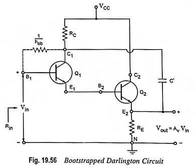
The noteworthy point is that RC is essential because in its absence RE would be shorted to ground. If the input signal changes by Vin then E2 changes by AvVin (assuming that reactance of C’ is negligible) and the collector changes by the same amount. Hence 1/hob is now effectively increased to 1/hob(1-Av) ≡ 400 MΩ for a voltage gain of 0.995.
An expression for the input resistance Rin of the bootstrapped Darlington circuit can be had by using the equivalent circuit shown in Fig 19.57.
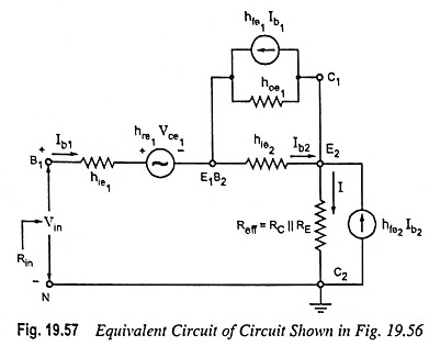
The effective resistance Reff between terminal E2 and ground is RC || RE. If hoeReff ≤ 0.1, then transistor Q2 may be represented by approximate hybrid model. However, the exact hybrid model, as shown in Fig. 19.57, must be used for Q2. Since 1/hoe1 >> hie2, hoe1 may be omitted from this figure. Solving for Vin/Ib1, we have
![]()
The above equation shows that the input resistance of the bootstrapped Darlington circuit is essentially equal to the product of the short-circuit current gains and the effective emitter resistance. If the transistor with the current gains of the order of magnitude of 100 are used and effective resistance as 5 kΩ, then input resistance obtained would be of the order of 50 MΩ.