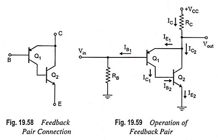
Feedback Pair Connection – Operation and its Equivalent Circuit:
The feedback pair connection (Fig. 19.58) is a two-transistor circuit that operates like the Darlington amplifier. It makes use of a PNP transistor driving an NPN transistor, the two devices acting much like one PNP transistor. Like Darlington amplifier the feedback pair connection also provides a very high current gain and high input resistance. Darlington amplifier and a feedback pair are used to provide complementary transistor operation. A practical circuit using a feedback pair connection is given in Fig. 19.59.
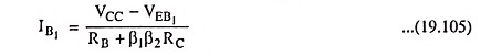
DC Bias: Applying Kirchhoff’s voltage law to base-emitter loop of transistor Q1 we have

Base current,
The collector current of transistor Q1 is given by
![]()
The collector current of transistor Q2 is given by
![]()
So that current through RC is
![]()
AC Operation:
AC equivalent circuit of the feedback pair (Fig. 19.59) is given in Fig. 19.60. Figure 19.60 (a) is drawn to indicate clearly each transistor and the base and collector resistor placement and ac equivalent for the purpose of analysis is shown in Fig. 19.60 (b).
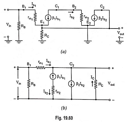
The ac input impedance seen looking into the base of transistor Q1 is determined [Fig. 19.60 (b)] as follows:
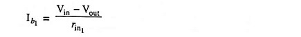
When
![]()
Thus we have
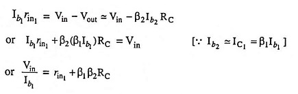
Including the base-bias resistance
![]()
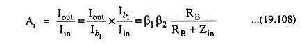
The ac current gain is determined as follows:
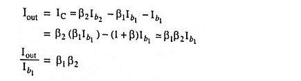
Including RB, the current gain is given by
The ac output impedance may be obtained by applying a voltage Vout with Vin set to zero. The resulting analysis gives that
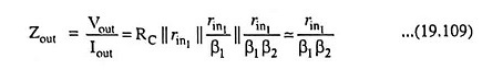
It results in low output impedance.
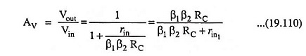
The ac voltage gain is determined as follows :
Output voltage
![]()
Also, output voltage,
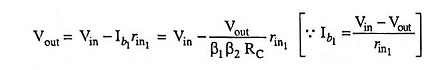
Voltage gain,