Cascade Transformer Connection:
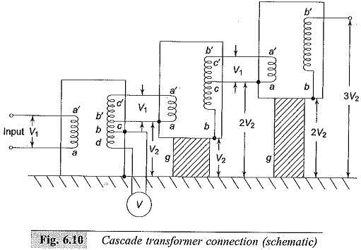
Figure 6.10 shows the Cascade Transformer Connection units in which the first transformer is at the ground potential along with its tank. The second transformer is kept on insulators and maintained at a potential of V2, the output voltage of the first unit above the ground. The high voltage winding of the first unit is connected to the tank of the second unit. The low voltage winding of this unit is supplied from the excitation winding of the first transformer, which is in series with the high voltage winding of the first transformer at its high voltage end.
The high voltage connection from the first transformer winding and the excitation winding terminal are taken through a bushing to the second transformer. In a similar manner, the third transformer is kept on insulators above the ground at a potential of 2V2 and is supplied likewise from the second transformer. The number of stages in this type of arrangement are usually two to four, but very often, three stages are adopted to facilitate a three-phase operation so that √3V2 can be obtained between the lines.
Where
V1 – Input Voltage
V2 – Output Voltage
g – Insulation support
aa′ – L.V. Primary winding
bb′ – H.V. Secondary winding
cc′ – Excitation winding
bd – Meter winding (200 to 500 V)
Supply to the units can be obtained from a motor-generator set or through an induction regulator for variation of the output voltage. The rating of the primary or the low voltage winding is usually 230 or 400 V for small units up to 100 kVA. For larger outputs, the rating of the low voltage winding may be 3.3 kV, 6.6 kV or 11 kV.
In Fig. 6.11, a second scheme for providing the excitation to the second and the third stages is shown. Isolating transformers Is1, Is2 and Is3 are 1 : 1 ratio transformers insulated to their respective tank potentials and are meant for supplying the excitation for the second and the third stages at their tank potentials. Power supply to the isolating transformers is also fed from the same a.c. input. This scheme is expensive and requires more space.
Transportation and assembly is easy. Also the construction is identical for isolating transformers and the high voltage Cascade Transformer Connection units. Three phase connection in delta or star is possible for three units. Testing transformers of ratings up to 10 MVA in Cascade Transformer Connection to give high voltages up to 2.25 MV are available for both indoor and outdoor applications.
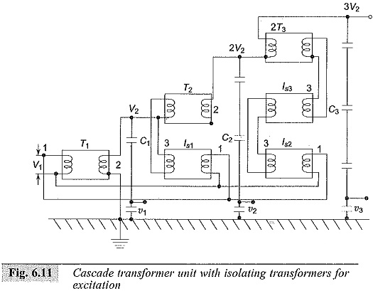
Cascade Transformer Connection unit with isolating transformers for excitation
T1,T2,T3 – Cascade transformer units
Is1,Is2,Is3 – Isolation transformer units
C1,C2,C3 – Capacitance voltage dividers for h.v. measurement after 1st, 2nd and 3rd stages
V1,V2,V3 – For metering after 1st, 2nd and 3rd stages
1. Primary (l.v. winding), 2. h.v. winding, 3. Excitation winding.
Testing of an H.V. apparatus or insulation always involves supplying of capacitive loads with very low power dissipation. Thus if C is the capacitance of the test object, V is the rms value of the nominal output voltage of the transformer at an angular frequency ω, then the nominal rating of the transformer in kVA will be P = K . V2 ωC, where K (> 1.0) is a factor to account for any extra capacitance in the test circuit like that of the measuring capacitance divider etc. K may have values of the order of 2 or more for very high voltages (> 1 MV). Typical capacitance values for high capacitance test objects like power transformers, cables, etc. are as follows:
![]()
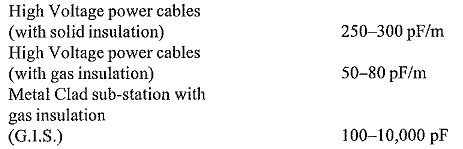
The charging currents for the test apparatus may range from 10 mA at 100 kV to a few milliamperes in the megavolt range. As such the transformers should have only a short time rating (10 to 15 min) for high power ratings, as compared to those–with nominal power ratings.
Large testing transformers rated for more than 1 MVA at 1 MV are nowadays designed for outdoor use only. The design is of the type mentioned in the second scheme and ensures that the units are enclosed by large-size metal rings to prevent corona, and are terminated with near spherical polycone electrodes. Modern test transformers are built to withstand transients during the flashover of the test object. However, particular care neet to be taken to see that steady state voltage distribution within the cascade units is uniform.
Sometimes reactor compensation may have to be provided for excessive load currents of capacitive nature. Cascade Transformer Connection are very expensive apparatus and are difficult to repair. Therefore it is necessary to limit the high short-circuit currents by using limiting reactors in the input stage.
Power Supply for AC Test Circuits:
Large Cascade Transformer Connection units are supplied power through a separate motor-generator set or by means of voltage regulators. Supply through a voltage regulator will be cheaper, and will be more flexible in the sense that the units in the cascade set can be operated in cascade, or in parallel, or as three-phase units. It is also necessary that the impedance of the voltage regulating transformer is low in all voltage positions, from the minimum to the rated value.