Voltage, Current and Power in 3 Phase Star Connection:
3 Phase Star Connection – Figure 9.21 shows a balanced three-phase, Y-connected system. The voltage induced in each winding is called the phase voltage (Vph). Likewise VRN, VYN and VBN represent the rms values of the induced voltages in each phase. The voltage available between any pair of terminals is called the line voltage (VL). Likewise VRY, VYB and VBR are known as line voltages. The double subscript notation is purposefully used to represent voltages and currents in polyphase circuits. Thus, VRY indicates a voltage V between points R and Y, with R being positive with respect to point Y during its positive half cycle.
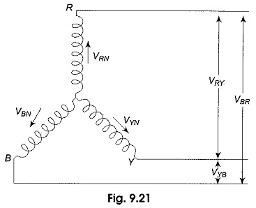
Similarly, VYB means that Y is positive with respect o point B during its positive half cycle; it also means that VRY = -VYR.
Voltage Relation:
The phasors corresponding to the phase voltages constituting a three-phase system can be represented by a phasor diagram as shown in Fig. 9.22.
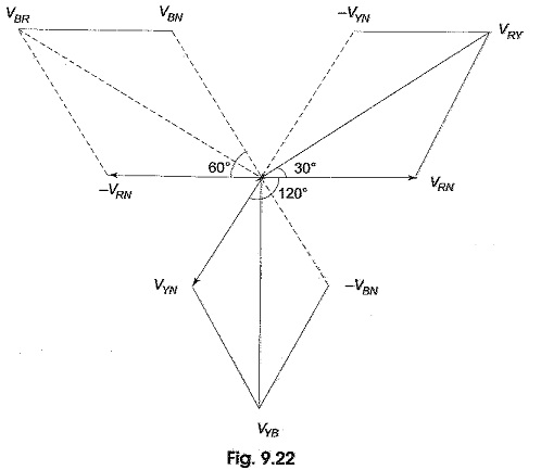
From Fig. 9.22, considering the lines R, Y and R, the line voltage VRY is equal to the phasor sum of VRN and VNY which is also equal to the phasor difference of VRN and VNY (VNY =-VYN). Hence, VRY is found by compounding VRN and VYN reversed. To subtract VYN from VRN, we reverse the phasor VYN and find its phasor sum with VRN as shown in Fig. 9.22. The two phasors, VRN and -VYN are equal in length and are 60° apart.
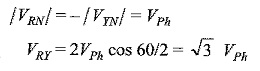
Similarly, the line voltage VYB is equal to the phasor difference of VYN and VBN, and is equal to √3 VPh. The line voltage VBR is equal to the phasor difference of VBN and VRN and is equal to √3 VPh. Hence, in a balanced 3 Phase Star Connection system
- Line voltage = √3 VPh
- All line voltages are equal in magnitude and are displaced by 120°, and
- All line voltages are 30° ahead of their respective phase voltages (from Fig. 9.22).
Current Relations:
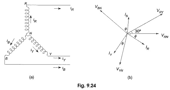
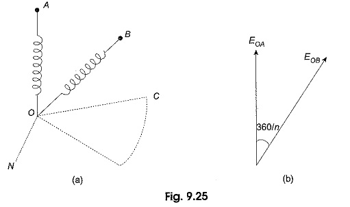
Figure 9.24(a) shows a balanced three-phase, wye-connected system indicating phase currents and line currents. The arrows placed alongside the currents IR, IY and IB flowing in the three phases indicate the directions of currents when they are assumed to be positive and not the directions at that particular instant. The phasor diagram for phase currents with respect to their phase voltages is shown in Fig. 9.24(b). All the phase currents are displaced by 120° with respect to each other, ‘Φ’ is the phase angle between phase voltage and phase current (lagging load is assumed). For a balanced load, all the phase currents are equal in magnitude. It can be observed from Fig. 924(a) that each line conductor is connected in series with its individual phase winding. Therefore, the current in a line conductor is the same as that in the phase to which the line conductor is connected.
![]()
It can be observed from Fig. 9.24(b) that the angle between the line (phase) current and the corresponding line voltage is (30 + Φ)° for a lagging load. Consequently, if the load is leading, then the angle between the line (phase) current and corresponding line voltage will be (30 — Φ)°.
Power in the Star-Connected Network:
The total active power or true power in the three-phase load is the sum of the powers in the three phases. For a balanced load, the power in each load is the same; hence total power = 3 x power in each phase
![]()
It is the usual practice to express the three-phase power in terms of line quantities as follows.
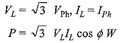
or √3 VLIL cos Φ is the active power in the circuit.
Total reactive power is given by
![]()
Total apparent power or volt-amperes
![]()
N-Phase Star System:
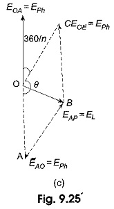
It is to be noted that star and mesh are general terms applicable to any number of phases; but wye and delta are special cases of star and mesh when the system is a three-phase system. Consider an n-phase balanced star system with two adjacent phases as shown in Fig. 9.25(a). Its vector diagram is shown in Fig. 9.25(b).
The angle of phase difference between adjacent phase voltages is 360°/n. Let EPh be the voltage of each phase. The line voltage, i.e. the voltage between A and B is equal to EAB = EL = EAO + EOB. The vector addition is shown in Fig. 9.25 (c). It is evident that the line current and phase current are same.
![]()
Consider the parallelogram OABC.
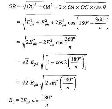
The above equation is a general equation for line voltage, for example, for a three-phase system, n = 3 EL = 2 Eph sin 60° = √3 Eph.