Fixed Bias Circuit Diagram – Advantages and Disadvantages:
Fixed Bias Circuit Diagram shown in Fig. 12.5 uses two batteries VBB and VCC. The battery VBB gives potential to the base terminal through resistance RB (of the order of hundred kΩ) and battery VCC supplies power to the collector through resistance RC (of the order of kΩ).
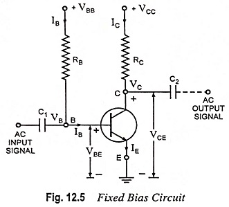
The base current can be determined by applying Kirchhoff’s second law for the branch circuit, starting from battery VBB to ground.
![]()
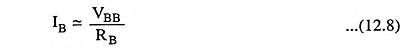
Since VBE is very small (0.7 V in case of silicon transistor and 0.3 V in case of Ge transistor) in comparison to VBB, not much error will be committed if it is neglected. The base current is then given by the simple expression
The supply voltage VBB being of fixed value—once the resistance RB is chosen—the base current IB is also fixed. Hence the name fixed bias circuit is given.
The collector-emitter section consists of the supply battery VCC, the collector resistor and the transistor collector-emitter junction. The currents through the collector and emitter are about the same since IB is very small in comparison to either. For linear amplifier operation, the collector current will be β times base current, where β is the transistor current gain i.e.,
![]()
The base current IB is determined from the operation of the base-emitter section of the circuit. The collector current, as shown above, will be β times the base current and not at all dependent on the resistance in the collector circuit. Thus collector current lC is controlled by base-emitter section of the circuit.
Applying Kirchhoff’s second law to the branch circuit starting from VCC to ground.
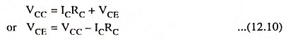
The quiescent point is given by IC, VCE.
The coupling capacitors C1 and C2 have reactances quite small at the frequency of ac signal, so that very little voltage drop of ac signal takes place across them. These capacitors are open circuit for direct currents, so that dc biasing potentials of this amplifier stage do not affect the circuits connected at the input as well as output terminals.
The fixed bias circuit is the simplest way to bias a transistor, but from stability point of view it is the worst circuit, because with the rise in temperature of transistor, β changes and also there is increase of leakage current and drop in VBE value.
Since base current IB controls the collector current IC and IC is equal to βIB, with the change in the value of β, IC changes (IB remaining unchanged) and the operating point gets shifted.
The circuit shown in Fig. 12.5 may be modified by using a single battery, as shown in Fig. 12.2. From the practical point of view, it is always preferable to have an electronic circuit operated from a single battery.
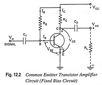
The expressions for IB, IC and VCE are given below
![]()
Stability Factor S:
As we know from earlier section, the stability factor
![]()
and in Fixed Bias Circuit method IB is independent of IC, as obvious from Eq. (12.8) or Eq. (12.11), so stability factor is given as
![]()
If β = 150, then S = 151 which means that collector current IC increases 151 times as much as ICO. Such a large value of S makes thermal runaway, a definite possibility with this circuit.
Advantages and Disadvantages:
Though this biasing circuit is very simple, as very few components (only two resistors and one battery) are required, biasing conditions can be easily set, the calculations are simple and there is no loading of the source by the biasing circuit, as no resistor is used across base-emitter junction but this method of biasing is rarely used. This is due to the following reasons.
- This method provides poor stability, as there is no means to stop a self increase in collector current IC owing to temperature rise and individual variations. For example, if β increases either due to temperature rise or due to replacement of transistor, then collector current, lC also increases by the same factor as base current IB is constant.
- There are good chances of thermal runaway. This is due to high stability factor S.