Primary Resistance Starter – Operation, Wiring Diagram, Advantages and Disadvantages:
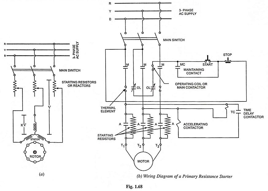
This method of primary resistance starter of a polyphase cage motor is very simple and provides smooth acceleration of the motor. In this method of starting of a 3-phase squirrel cage induction motor reduced voltage is obtained by means of resistors (or reactors) that are connected in series with each stator lead, as shown in Fig. 1.68, during the starting period. The voltage drop in resistors (or reactors) causes a reduced voltage across the motor terminals. As the motor picks up the speed, the resistors (or reactors) are cut out in steps and finally short circuited when the motor attains the operating speed.
The primary resistance starter method is quite similar to the dc shunt motor starter with its series armature resistor, because both provide a voltage drop between the voltage supply and the motor terminals. There are, however, some very important differences. In a dc shunt motor the starting torque is directly proportional to the starting armature current whereas in case of a polyphase induction motor the torque varies as the square of the motor terminal voltage i.e., there is a far greater reduction of starting torque for an equivalent reduction of starting current.
Although the initial cost of reactors is high in comparison to that of resistors, reactor starting is preferred because this method incurs small power losses and is more effective in reducing the voltage applied to the stator at starting.
The advantages and disadvantages of this method of starting of cage motors are given below:
Advantages:
- Smooth acceleration.
- High power factor during start.
- Less expensive than auto-transformer starter in lower output ratings.
- Closed transition starting.
- Available with as many as 7 accelerating points.
Disadvantages:
- Resistors give off heat.
- Low torque efficiency.
- Starting duration usually exceeds 5 seconds, so needs expensive resistors.
- Starting voltage is difficult to adjust to meet varying conditions.
Circuit diagram of a magnetically operated primary resistance starter is illustrated in Fig. 1.68 (b).
Overload and undervoltage protections are provided in the same manner as in the direct-on-line starter.
In the starter described above, the starting resistors are cut out in one step. Starters are also available, in which arrangement is to cut out starting resistances in several steps and thus to give smooth acceleration with less line disturbance.
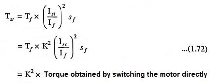
If the normal supply phase voltage = V volts and by using line resistance starter the voltage is reduced to KV volts, then starting current is also reduced in the same ratio i.e., starting current Ist = K Isc where Isc is the short-circuit current.
Starting torque,
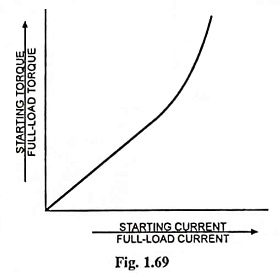
This method finds its application in some cases where only very low starting torques are required. A curve plotted between the starting-current/full-load current and the starting-torque/full load torque in case of stator resistance method of starting of induction motor is depicted in Fig. 1.69.