Induction Motor Equivalent Circuit:
Induction Motor Equivalent Circuit – The behavior of the induction machine was studied in terms of the basic field phenomenon. The attempt here was purposely focused on the transformer analogy of induction motor. Certain facts established so far are summarized below:
1.

where E2 = standstill rotor emf.
Further I’2 flows into the positive terminal of E1 and I2 flows out of the positive terminal of E2. Also, I2 as seen from the stator is the current of stator frequency f and is in phase with I’2, the component of current drawn by the stator to balance the rotor mmf F2.
2. Like in a transformer, the magnetizing current component Im of the stator current lags the stator induced emf E1 by 90°.
3. The induction motor is not merely a transformer which changes voltage and current levels. It in fact behaves like a generalized transformer in which the frequency is also transformed in proportion to slip such that the rotor induced emf is sE2 and rotor reactance is sX2.
The Induction Motor Equivalent Circuit can now be drawn on a per phase basis as in Fig. 9.7(a) wherein the series elements (lumped) of the stator resistance and leakage reactance have been included in the model. The transformer linking the stator and rotor circuits is an ideal generalized transformer in which the standstill rotor voltage E2 and rotor current I2 are linked to the stator quantities via transformation ratio a, while the frequency parameter appears in the rotor circuit through the slip s, a mechanical parameter. The mechanical power output appears at the shaft indicated in the figure.
The rotor circuit can be referred to the stator side by a two-step process modifying the rotor circuit so that the turn-ratio becomes unity and then carrying out a frequency transformation resulting in an equivalent rotor circuit at the stator frequency.
By multiplying the rotor voltage by a and the rotor current by 1/a, the rotor impedance gets modified to
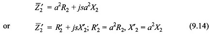
In this transformation power remains invariant. The rotor circuit, after carrying out this step, is drawn in Fig. 9.7(b). This reduces the rotor to an equivalent rotor having a unity turn-ratio with the stator.
From the equivalent rotor circuit of Fig. 9.7(b)

Dividing both numerator and denominator by s

This simple trick refers the rotor circuit to the stator frequency. The modified rotor circuit is now drawn in Fig. 9.7(c) wherein since both the rotor and stator circuit have the same frequency, the ideal transformer is now a stationary unit-ratio transformer. It is also noticed that in referring the rotor circuit to the stator frequency the reactance becomes constant (X’2) and the resistance becomes variable (R’2/s). The transformation of Eq. (9.15b) is not power-invariant (voltage changes while current remains the same). The power transferred to the secondary now accounts for both the rotor copper-loss and mechanical power output (in electrical form). This is in contrast to Fig. 9.7(a) where mechanical power is taken off via a shaft.
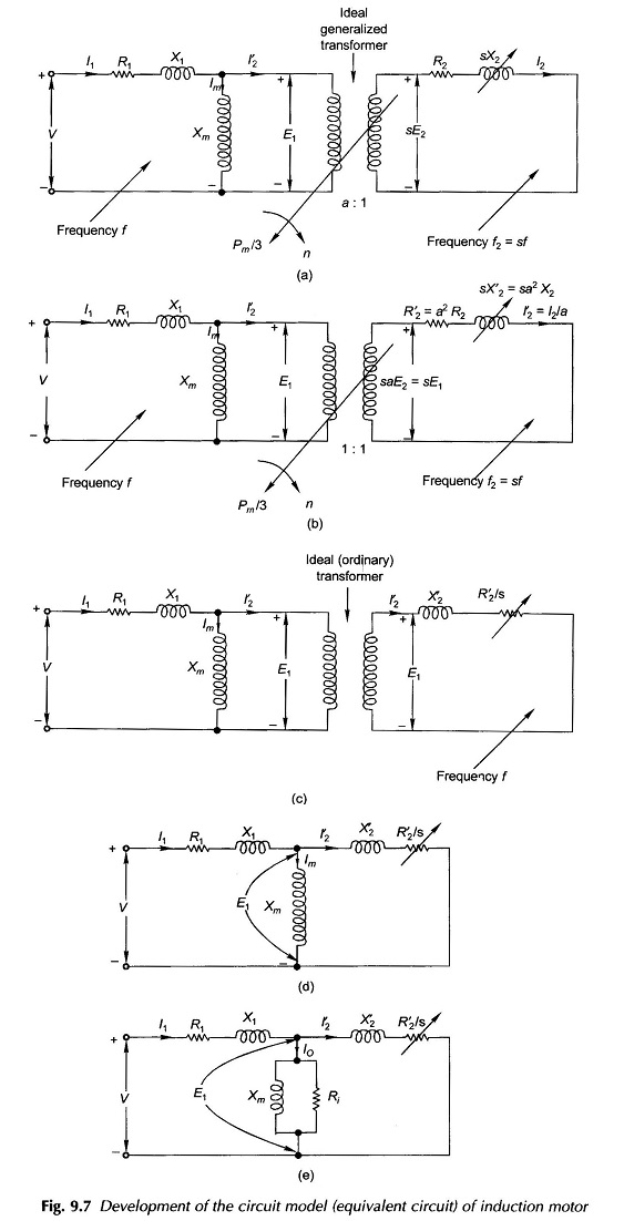
As a last step in Induction Motor Equivalent Circuit development, the ideal (ordinary) unit-ratio transformer can now be dispensed with resulting in the Circuit Model of Fig. 9.7(d).
The representation of iron-loss in the stator can be heuristically introduced in the circuit model of Fig. 9.7(d) by placing a resistance Ri in parallel with Xm as in the transformer circuit model. This Induction Motor Equivalent Circuit is drawn in Fig. 9.7(e).
If R’2, is separated from R’2/s to represent the rotor copper-loss as a separate entity, the circuit model can be drawn as in Fig. 9.8(a) in which the variable resistance R’2(1/s – 1) represents the mechanical output in electrical form. Alternatively the Circuit Model of Fig. 9.8(b) could be used (this corresponds to Fig. 9.7(d) wherein the iron loss resistance Ri is omitted and this loss would be subtracted from the gross mechanical output (power absorbed by R’2(1/s – 1)). This amounts to certain approximation which is quite acceptable in the normal range of slip in an induction motor. Further the parameters of this circuit (which does not need the value of Ri) can be easily obtained by two non-loading tests.
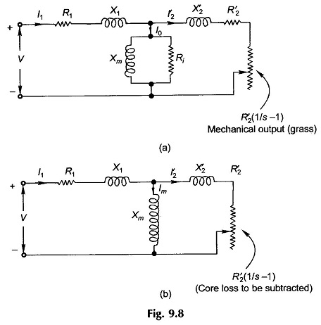
The Circuit Model of Fig. 9.8(b) would be used for most of the discussion that follows. It may be noted here that the power dissipated in R’2(1/s – 1) includes the core loss, which must be subtracted from it to obtain the gross mechanical power. For getting net mechanical power output, the windage and friction loss must be further subtracted from it. The core loss and windage and friction loss together are lumped as rotational loss as both these losses occur when the motor is running. The rotational loss in an induction motor is substantially constant at constant applied voltage and motor speed varies very little from no-load to full load.
Note: Net mechanical power = shaft power