Harmonic Distortion in Power Amplifier – Waveform and Derivation:
Harmonic Distortion in Power Amplifier – Output signal variations of less than 360° of the signal cycle are considered to have distortion. This means that the output signal is no longer just an amplified version of the input signal but in some way a distorted or changed from that of the input. The poor quality of music coming from a radio or hi-fi system with the music or voice no longer sounding like that which was originally recorded or transmitted is the result of distortion.
A good amplifier should not only provide an enlarged version of the input signal at the output, but should also provide a faithful reproduction of the input waveforms. One type of distortion that is common to most of the amplifiers is called the amplitude or harmonic distortion, which is caused due to nonlinearity of the active device employed for amplification. The active device (semiconductor device or tube) used for amplification may not increase equally all portions of the input signal over its positive and negative excursions. Harmonic distortion in power amplifier increases as we go from class A operation to class C operation. Even in class A operation some distortion occurs.
When nonlinear distortion is present, the output waveform contains components of frequencies which are harmonics (integer multiples) of the input signal frequency. There may be present second, third and higher order harmonic components, but the most important in terms of the amount of distortion for the classes of operation we will consider is the second harmonic. For a signal occurring in class AB or class B, the distortion may be mainly even harmonics of which the second harmonic component is the greatest.
An instrument such as a spectrum analyzer permits the measurement of the harmonics present in the signal by providing a display of the fundamental component of signal and a number of harmonics on a CRT screen. Similarly, a wave analyzer instrument allows a more precise measurement of the harmonic components of a distorted signal by filtering out each of these components and providing a reading of these components, one at a time. In any case the technique of considering any distorted signal as containing a fundamental component and harmonic components is practical and useful.
Determination of Second Harmonic Distortion:
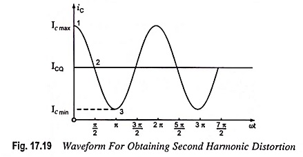
A collector current waveform is shown in Fig. 17.19, with the quiescent, minimum and maximum, signal levels, and the time they occur marked on the waveform. An equation which approximately describes the distorted signal waveform is
![]()
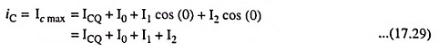
The given current waveform contains the original quiescent current ICQ, that occurs with zero input signal, an additional dc current I0, due to the nonzero average of the distorted signal; the fundamental component of the distorted ac signal I1; and a second harmonic component I2, at twice the fundamental frequency. Although other harmonics are present, only the second is considered here. Equating the resultant current from Eq. (17.28) at a few points in the cycle to that shown on the current waveform we get
At point 1 i.e., when ωt = 0
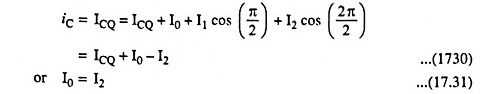
At point 2 i.e., when ωt = π/2
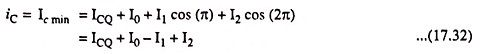
At point 3 i.e., when ωt = π
Solving Eqs. (17.29), (17.31) and (17.32) we get
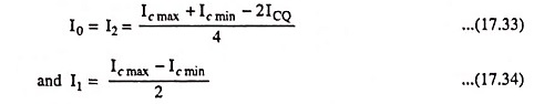
By definition the per cent of the second Harmonic distortion in power amplifier is given as
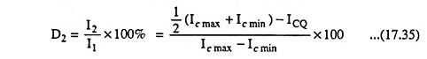
The second Harmonic distortion in power amplifier is the per cent of the second harmonic component present in the output current waveform with respect to the amount of the fundamental component. Obviously, 0% distortion is the ideal condition of no distortion.
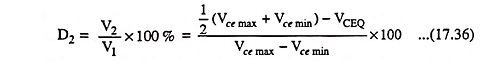
In a similar way, the per cent of second Harmonic distortion in power amplifier present in the output voltage waveform w.r.t. the amount of the fundamental component can be determined and is given as
Five Point Method of Determination of Harmonic Distortion in Power Amplifiers
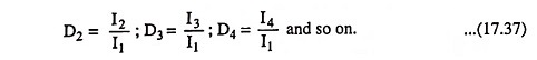
The method of determination of second harmonic distortion is called the 3-point method as it involved equating the assumed waveform of the output current/voltage to the measured voltage at three points in the signal cycle. Using an assumed output signal equation containing more harmonic terms, along with choosing more points in the waveform, results in obtaining relations for the magnitude of the harmonic components at higher harmonic frequencies. Using a 5-point method provides the dc component, first harmonic (fundamental), second harmonic, third harmonic, and fourth harmonic components. The Harmonic distortion in power amplifier for each of these components is then defined as
Total distortion may be defined, in general, using the individual distortion components
![]()
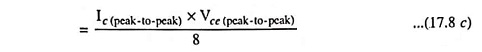
When distortion occurs, the output power computed on the basis of non-distortion is no longer correct. For example, the power computed from Eq. (17.8c) provides output power only for the non-distorted case. In case of a distorted output, the output power due to the fundamental component of the distorted signal is given as
![]()
Similarly,
![]()
Total power due to all harmonic components of the distorted signal is given as
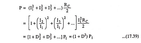
If the total distortion is 10% i.e., 0.1, then the total power is [1 + (0.1)2] P1 = 1.01 P1

i.e., a 10% distortion represents a power increase of only 1% of the fundamental. Thus, only a small error is introduced in using only the fundamental term P1 for determination of the output power.