Nonlinear Distortion Measurements:
One of the methods of Nonlinear Distortion Measurements consists of simultaneously applying two sinusoidal voltages of different frequencies to the amplifier input and observing the sum, difference and various combination frequencies that are produced by the non-linearity of the amplifier. This method of Nonlinear Distortion Measurements is called the intermodulation method.
The two signals may be combined under many different conditions, but two cases are important.
In the first case, a low frequency test signal and a high frequency test signal of somewhat smaller amplitude are simultaneously applied to the amplifier. If Nonlinear Distortion Measurements and its effects are present, then the amplification that the high frequency component f2 experiences will vary at the frequency f1 of the low frequency signal, as shown in Fig. 16.6.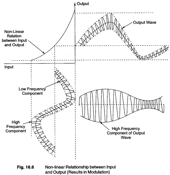
Hence the signal of frequency f2 in the amplifier output is modulated at the low frequency f1. The amount of distortion is then expressed in terms of the modulation experienced by the high frequency wave, according to the relation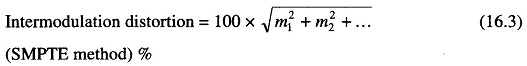
where
- m1 = degree of modulation that the output component of frequency f2 experiences at frequency f1
- m2 = corresponding modulation of f2 at a frequency 2f1.
This particular method of employing two signals to determine Nonlinear Distortion Measurements is widely used in AF systems. It is commonly referred to as the SMPTE intermodulation method, since it has been standardised by the Society of Motion Pictures and Television Engineers (SMPTE).
(An alternative method of explaining this situation is to consider that the non-linear action of the amplifier produces sum and difference frequencies, (f1 + f2) and (f1 — f2) respectively. These frequency components, together with f2, can be thought of as representing the side bands and a carrier respectively, thus forming a wave of carrier frequency f2 modulated at frequency f1. If the Nonlinear Distortion Measurements is also sufficient to produce second order combination frequencies f2 + 2f1, the modulation envelope then contains a component that is the second harmonic of f1. The modulation envelope is then not sinusoidal.)
The block diagram for the setup of determining intermodulation by the SMPTE method is shown in Fig. 16.7.
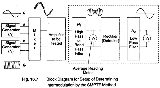
The system consists of two signal generators, generating frequencies f1 and f2 respectively, and combining these two outputs from the signal generators. The combining systems may take any of a number of forms, such as a transformer with centre tapped primary, or two amplifier active devices with separate inputs but common output load impedance. (Alternatively, it is possible to use a two frequency signal generator specially designed for intermodulation test.)
The network N1 separates the high frequency (f2) and its side bands from other frequency components that may be present in the amplifier output. Voltmeter V1 measure the amplitude of the resulting modulated wave, i.e. it measures the carrier amplitude E2.
The modulation envelope is determined by rectifying (detecting) the modulation wave, separating the modulation frequency component of the envelope by a low pass filter N2, and determining the amplitude of the modulation component by voltmeter V2. The dotted block indicates a system for measuring the characteristics of a modulated wave. Calibration can be carried out by applying known voltages of frequencies f1 and f2 to terminals a and b.
In such a measuring system, shown in Fig. 16.7, the normal practice is to make the low frequency test signal at least four times as large as the high frequency test signal applied to the system. The low frequency used is about 50 — 100 Hz, while the high frequency is typically about 5 kHz or more.
The low pass filter N2, must have a sufficient band width to pass second order side bands, that is, a cutoff frequency greater than 2f1. Band pass filter N1 must have a corresponding band width greater than 4f1.
The voltmeter V1 used must be an average-reading type and voltmeter V2 must be a square law device. An average reading meter, such as a copper oxide rectifier instrument gives sufficiently accurate results for ordinary requirements. In no case should voltmeter V2 be a peak reading meter.
The value of the intermodulation distortion determined by the SMPTE method depends basically on the non-linearity met by the low frequency test signal, because this signal is much larger under standard test conditions. The observed intermodulation distortion is largely dependent on the value of the high frequency f2, but depends at least slightly on the value of f1.