Cathode Ray Oscillograph for Impulse Measurements:
Modern Cathode Ray Oscillograph for Impulse Measurements are sealed tube, hot cathode oscilloscopes with photographic arrangement for recording the waveforms. The cathode ray oscilloscope for impulse work normally has input voltage range from 5 m V/cm to about 20 V/cm. In addition, there are probes and attenuators to handle signals up to 600 V (peak to peak). The bandwidth and rise time of the oscilloscope should be adequate. Rise times of 5 ns and bandwidth as high as 500 MHz may be necessary.
Sometimes high voltage surges test oscilloscopes do not have vertical amplifier and directly require an input voltage of 10 V. They can take a maximum signal of about 100 V (peak to peak) but require suitable attenuators for large signals.
Oscilloscopes are fitted with good cameras for recording purposes. Tektronix model 7094 is fitted with a lens of 1 : 1.2 polaroid camera which uses 10.000 ASA film which possesses a writing speed of 9 cm/ns.
With rapidly changing signals, it is necessary to initiate or start the oscilloscope time base before the signal reaches the oscilloscope deflecting plates, otherwise a portion of the signal may be missed. Such measurements require an accurate initiation of the horizontal time base and is known as triggering. Oscilloscopes are normally provided with both internal and external triggering facility. When external triggering is used, as with recording of impulses, the signal is directly fed to actuate the time base and then applied to the vertical or Y deflecting plates through a delay line. The delay is usually 0.1 to 0.5 μs.
The delay is obtained by:
1. A long interconnecting coaxial cable 20 to 50 in long. The required triggering is obtained from an antenna whose induced voltage is applied to the external trigger terminal.
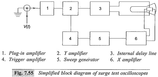
2.The measuring signal is transmitted to the CRO by a normal coaxial cable. The delay is obtained by an externally connected coaxial long cable to give the necessary delay. This arrangement is shown in Fig. 7.55.
3.The impulse generator and the time base of the CRO are triggered from an electronic tripping device. A first pulse from the device starts the CRO time base and after a predetermined time a second pulse triggers the impulse generator.