Standing Wave Ratio Measurements:
Standing wave are created along the length of a transmission line due to the mismatch between the characteristic impedance Z0 and the terminating impedance of the transmission line.
The actual voltage E on the line at any point is the sum (Ei + Er) of the voltage of the incident and reflected waves at the point. This results in a voltage distribution on the line, such as illustrated in Fig. 20.8, called a standing wave pattern.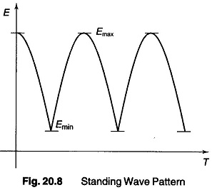
If on a certain line there is both an incident and a reflected wave, a voltage maxima occurs at points where the two waves are in the same phase, and a minima at points where the two waves are in phase opposition.
When the difference between maxima and minima is more pronounced, the larger the reflection coefficient. In particular, when the reflection coefficient of the load is unity, the minima are very deep, while when the reflection coefficient of the load is zero, there is no standing wave pattern.
The distance between adjacent minima (or maxima) is exactly half the line wavelength.
The ratio of the maximum to the minimum value of voltages (or currents) in the standing wave pattern is termed the standing wave ratio.
Voltage standing wave ratio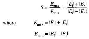
If the line has no attenuation, the standing wave ratio, S, is the same everywhere. (If the line has losses, S decreases with increasing distance from the load.)
If directional couplers are used for measurement of the standing wave ratio, then V2 indicates |Ei|, V1 indicates |Er| and the standing wave ratio is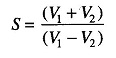
Measurement of Standing Wave Ratio Using Directional Couplers
A directional coupler is a device, which when coupled to a transmission line or waveguide, responds only to the wave travelling in a particular direction on the primary transmission system, while being unaffected by a wave travelling in the opposite direction on the primary line.
Directional couplers serve as stable, accurate and relatively broad band coupling devices, which can be inserted into a transmission line to measure either incident or reflected power.
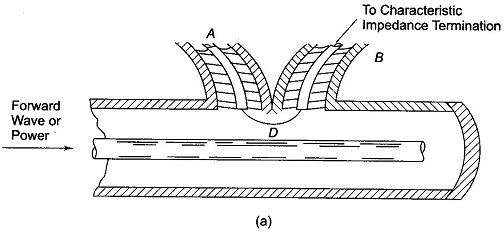
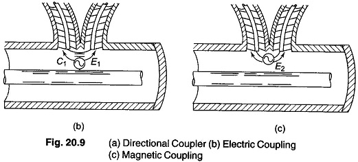
Referring to Fig. 20.9(a), the arrangement is so designed that a wave travelling towards the right in the co-axial line will induce a wave travelling towards the left in part A of the coupled co-axial cable, while a wave travelling towards the left in the co-axial line will produce no effect in part A of the secondary line.
The usefulness of a directional coupler in power measurement arises from the fact that in RF transmission systems each wave on the system can be considered as transmitting power in the direction in which the wave travels.
The net power transmitted towards the load is the difference between the power of the incident wave and the power associated with the reflected wave, i.e. the load power is the difference between the incident and reflected power at the load point.
The power represented by the induced wave in the directional coupler is a definite function of the power associated with the corresponding wave on the primary system. The ratio of the induced power to total power is termed as coupling, and is commonly expressed in decibels.
A single directional coupler determines the power flowing in only one direction on the primary line. By using two directional couplers on the same primary system, with one directional coupler responsive only to the wave travelling towards the load and the other responsive only to the reflected wave, one can separately measure the powers of the two primary waves, and by subtraction obtain the net load power.
In Fig. 20.9(a) the primary system is a co-axial line, and the secondary system consists of two co-axial lines A and B, interconnected by a loop D that projects into the primary line and is subjected to the simultaneous influence of the electric and magnetic fields that exist in it.
Consider now the case of a wave travelling towards the right on the primary system. The electric field of this wave induces a charge on the loop D that produces waves in both parts A and B of the secondary systems.
The equivalent circuit that describes this action is illustrated in Fig. 20.9(b) and consists of a voltage E1 that is applied to co-axial systems A and B in parallel through series capacitance C1, producing currents as indicated by the arrows.
The loop D links with the magnetic flux from the wave in the primary line, and therefore has a voltage E2 induced in series with it, as illustrated in Fig. 20.9(c).
This series voltage gives rise to waves in parts A and B of the secondary system, which are characterised by currents flowing in the direction indicated by the arrows.
The two waves in section A, produced by magnetic and electrostatic coupling respectively, are of the same polarity and hence add, while the two waves produced in section B are of opposite polarity, and so tend to cancel each other.
If the electric and magnetic couplings are so proportioned that the waves induced by the magnetic effect have the same amplitude as the waves induced by electric coupling, complete cancellation takes place in section B.
With a wave travelling on the right in the primary line, the net effect is to produce only one resultant wave in the secondary system, which travels in the direction of A. By terminating section A of the secondary system in its characteristic impedance, this induced wave is absorbed. (If a voltmeter is connected across it, it will read voltage V1.)
The relative magnitude of electric and magnetic coupling in Fig. 20.9(b) can be readily controlled by, the design of the coupling loop D. The electric coupling depends on the amount of electric field that terminates on the loop, and is hence determined by the length of the loop and the diameter of the conductor.
Similarly, the magnetic coupling is determined by the amount of magnetic flux that links with the loop, which is determined by the area enclosed between the loop and the outer conductor of the line, and the orientation of the loop with respect to the axis of the line.
Assuming that the coupling arrangement in Fig. 20.9(a) has been designed so that a wave travelling to the right on the primary system produces no induced wave in section B, consider the effect of a wave travelling to the left in the primary system.
The component waves induced in A and B by the electric and magnetic fields in the primary co-axial line will again be equal to each other, since their magnitudes are not affected by the direction of travel on the primary line.
However, the polarity of the wave produced by the magnetic coupling is now reversed with respect to the polarity of the induced wave resulting from electric coupling.
Accordingly, the two waves induced in A now cancel each other, while the two waves produced in B add. Hence, a wave travelling to the left in the primary line produces no effect in section A, but does produce an induced wave in section B. By terminating B of the secondary system in its characteristics impedance, this induced wave is absorbed. (Also, if a voltmeter is connected across it, voltage V2 is obtained.)
The final result is then that any wave that appears in section A is determined only by the wave travelling to the right in the primary system, and is independent of the presence or absence of a wave travelling to the left in the primary system. Hence, one has achieved a directional coupling system.
Directional couplers are extensively used for monitoring and measuring power in microwave systems.
In particular, radar transmitters have built in directional couplers for monitoring power. They are also used in the determination of reflection coefficients.
Two similar directional couplers can be used to measure the net power delivered to a load if arrangements are made such that one coupler samples the incident power and the other coupler extracts the same fraction of the reflected power. The difference in the power outputs of the two couplers then gives a measure of the load power. The reflection coefficient can be determined as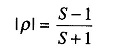
where S is the standing wave ratio given by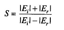
By terminating both A and B in well matched thermocouple elements, so that their opposed output is read on a micro ammeter, a wide band type of wattmeter can be realized for measuring the power in an arbitrary load.