Power Flow through Transmission Line:
So far the transmission line performance equation was presented in the form of voltage and current relationships between sending-and receiving-ends. Since loads are more often expressed in terms of real (watts/kW) and reactive (VARs/kVAR) power, it is convenient to deal with transmission line equations in the form of sending- and receiving-end complex power and voltages. While the problem of Power Flow through a Transmission Line in a general network will be discussed later, the Power Flow through Transmission Line principles involved are illustrated here through a single transmission line (2-node/2-bus system) as shown in Fig. 5.17.
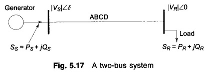
Let us take the receiving-end voltage as a reference phasor (VR = |VR| ∠0°) and let the sending-end voltage lead it by an angle δ(VS = |VS| ∠δ). The angle δ is known as the torque angle.
The complex power leaving the receiving-end and entering the sending-end of the transmission line can be expressed as (on per phase basis)
Receiving- and sending-end currents can, however, be expressed in terms of receiving- and sending-end voltages as
![]()
Let A, B, D, the transmission line constants, be written as
![]()
Therefore, we can write

Substituting for IR in Eq. (5.54) we get
Similarly,

In the above equations SR and SS are per phase complex voltamperes, while VR and VS are expressed in per phase volts. If VR and VS are expressed in kV line, then the three-phase receiving-end complex power is given by
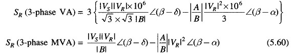
This indeed is the same as Eq. (5.58). The same result holds for SS. Thus we see that Eqs. (5.58) and (5.59) give the three-phase MVA if VS and VR are expressed in kV line.
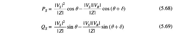
If Eq. (5.58) is expressed in real and imaginary parts, we can write the real and reactive powers at the receiving-end as
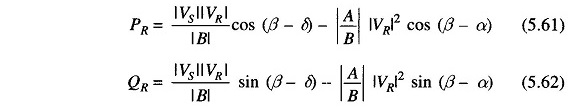
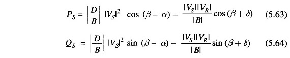
Similarly, the real and reactive powers at sending-end are
It is easy to see from Eq. (5.61) that the received power PR will be maximum at
![]()
such that
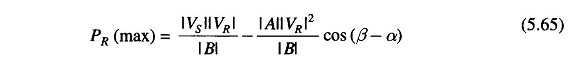
The corresponding QR (at max PR ) is
![]()
Thus the load must draw this much leading MVAR in order to receive the maximum real power.
Consider now the special case of a short line with a series impedance Z. Now
![]()
Substituting these in Eqs. (5.61) to (5.64), we get the simplified results for the short line as
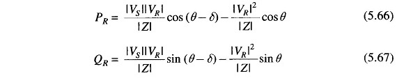
for the receiving-end and for the sending-end
The above short line equation will also apply for a long line when the line is replaced by its equivalent- π (or nominal- π) and the shunt admittances are lumped with the receiving-end load and sending-end generation.
From Eq.(5.66), the maximum receiving-end power is received, when δ = θ
so that
![]()
Now cos θ = R/|Z|,

Normally the resistance of a transmission line is small compared to its reactance (since it is necessary to maintain a high efficiency of transmission), so that θ = tan-1 X/R ≈ 90∘; where Z = R + jX. The receiving-end Eqs. (5.66) and (5.67) can then be approximated as
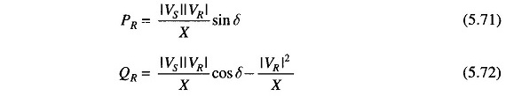
Equation (5.72) can be further simplified by assuming cos δ ≈ 1, since δ is normally small. Thus
![]()
Let |VS| – |VR| = |ΔV|, the magnitude of voltage drop across the transmission line.

Several important conclusions that easily follow from Eqs. (5.71) to (5.74) are enumerated below:
- For R ≈ 0 (which is a valid approximation for a transmission line) the real power transferred to the receiving-end is proportional to sin δ ( ≈ δ for small values of δ ), while the reactive power is proportional to the magnitude of the voltage drop across the line.
- The real power received is maximum for δ = 90° and has a value |Vs||VR|/X. Of course, δ is restricted to values well below 90° from considerations of stability.
- Maximum real power transferred for. a given line (fixed X) can be increased by raising its voltage level. It is from this consideration that voltage levels are being progressively pushed up to transmit larger chunks of Power Flow through Transmission Line over longer distances warranted by large size generating stations. For very long lines voltage level cannot be raised beyond the limits placed by present-day high voltage technology. To increase power transmitted in such cases, the only choice is to reduce the line reactance. This is accomplished by adding series capacitors in the line. Series capacitors would of course increase the severity of line over voltages under switching conditions.
- As said in 1 above, the VARs (lagging reactive power) delivered by a line is proportional to the line voltage drop and is independent of δ. Therefore, in a transmission system if the VARs demand of the load is large, the voltage profile at that point tends to sag rather sharply. To maintain a desired voltage profile, the VARs demand of the load must be met locally by employing positive VAR generators (condensers).
A somewhat more accurate yet approximate result expressing line voltage drop in terms of active and reactive Power Flow through Transmission Line can be written, i.e.
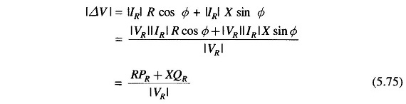
This result reduces to that of Eq. (5.74) if R = 0.