Switching Surges in Transmission Line:
Till the time when the transmission voltages were about 220 kV and below, over-voltages due to lightning were of very high order and overvoltages generated inside the system were not of much consequence. In later years, with increase in transmission voltages (400 kV and above), the overvoltages generated inside the system reached the same order of magnitude as those of lightning overvoltages, or higher. Secondly, the overvoltages thus generated last for longer durations and overvoltages, the switching and other types of overvoltages depend on the normal voltage of the system and hence increase with increased system voltage. In insulation co-ordination, where the protective level of any particular kind of surge diverter is proportional to the maximum voltage, the insulation level and the cost of the equipment depends on the magnitudes of these overvoltages. In the EHV range, it is the Switching Surges in Transmission Line and other types of overvoltages that determine the insulation level of the lines and other equipment and consequently, they also determine their dimensions and costs.
Origin of Switching Surges:
The making and breaking of electric circuits with switchgear may result in abnormal overvoltages in power systems having large inductances and capacitances. The overvoltages may go as high as six times the normal power frequency voltage. In circuit breaking operation, Switching Surges in Transmission Line with a high rate of rise of voltage may cause repeated restriking of the arc between the contacts of a circuit breaker, thereby causing destruction of the circuit breaker contacts. The Switching Surges in Transmission Line may include high natural frequencies of the system; a damped normal frequency voltage component, or the restriking and recovery voltage of the system with successive reflected waves from terminations.
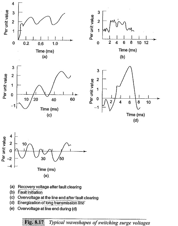
Characteristics of Switching Surges:
The waveshapes of Switching Surges in Transmission Line are quite different and may have origin from any of the following sources.
-
De-energizing of transmission lines, cables, shunt capacitor, banks, etc.
-
Disconnection of unloaded transformers, reactors, etc.
-
Energization or reclosing of lines and reactive loads.
-
Sudden switching off of loads.
-
Short circuits and fault clearances.
-
Resonance phenomenon like ferro-resonance, arcing grounds, etc.
Typical waveshapes of switching surges are given in Figs 8.14a to e.
From the figures of the switching surges it is clear that the overvoltages are irregular (oscillatory or unipolar) and can be of high frequency or power frequency with its harmonics. The relative magnitudes of the overvoltages may be about 2.4 p.u. in the case of transformer energizing and 1.4 to 2.0 p.u. in Switching Surges in Transmission Line.
Switching Overvoltages in EHV and UHV Systems:
The insulation has the lowest strength for Switching Surges in Transmission Line with regard to long air gaps. Further, switching overvoltages are of relatively higher magnitudes as compared to the lightning overvoltages for UHV systems. Overvoltages are generated in EHV systems when there is a sudden release of internal energy stored either in the electrostatic form (in the capacitance) or in the electromagnetic form (in the inductance). The different situations under which this happens are summarised as
-
interruption of low inductive currents (current chopping) by high speed circuit breakers. This occurs when the transformers or reactors are switched off
-
interruption of small capacitive currents, such as switching off of unloaded lines etc.
-
ferro-resonance condition. This may occur when poles of a circuit breaker do not close simultaneously
-
energization of long EHV or UHV lines.
Transient overvoltages in the above cases can be of the order of 2.0 to 3.3 p.u. and will have magnitudes of the order of 1200 kV to 2000 kV on 750 kV systems. The duration of these overvoltages varies from 1 to 10 ms depending on the circuit parameters. It is seen that these are of comparable or even higher than those that occur due to lightning. Sometimes the overvoltages may last for several cycles. The other situations of switching that give rise to switching overvoltages of short duration (0.5 to 5 ins) and lower magnitudes (2.0 to 2.5 p.u.) are:
-
single pole closing of circuit breaker
-
interruption of fault current when the L-G of L-L fault is cleared
-
resistance switching used in circuit breakers
-
switching lines terminated by transformers
-
series capacitor compensated lines
-
sparking of the surge diverter located at the receiving end of the line to limit the lightning overvoltages
The overvoltages due to the above conditions are studied or calculated from
-
mathematical modelling of a system using digital computers
-
scale modelling using transient network analysers
-
by conducting field tests to determine the expected maximum amplitude of the overvoltages and their duration at different points on the line.
The main factors that are investigated in the above studies are
-
the effect of line parameters, series capacitors and shunt reactors on the magnitude and duration of the transients.
-
the damping factors needed to reduce the magnitude of overvoltages
-
the effect of single pole closing, restriking and switching with series resistors in circuit breakers on the overvoltages, and
-
the lightning arrester sparkover characteristics.
-
It is necessary in EHV and UHV systems to control the Switching Surges in Transmission Line to a safe value of less than 2.5 p.u. or preferably to 2.0 p.u. or even less.
The measures taken to control or reduce the overvoltages are
-
one step or multi step energisation of lines by preinsertion of resistors,
-
phase controlled closing or circuit breakers with proper sensors,
-
drainage of trapped charges on long lines before the reclosing of the lines, and
-
limiting the overvoltages by using surge diverters.
-
The first three methods, if used properly will limit the switching overvoltages to 1.5 to 2.0 p.u.