Switching Transients in Transformer | Transformer Inrush Current:
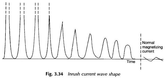
Switching Transients in Transformer – In the earlier discussion earlier steady-state operation was assumed so that v1 and Φ are both sinusoidal, Φ lagging v1 by 90° as shown once again in Fig. 3.33(a). The Φ – i0 relationship is shown in Fig. 3.33(b). The normal exciting current under these conditions is about 0.05 pu if the transformer is designed with Bmax about 1.4 T.
When the voltage v1 is switched on to the transformer, the core flux and the corresponding exciting current undergo a transient before reaching steady-state values. The severity of the Switching Transients in Transformer is related to the instant when the voltage wave is switched on; the worst conditions being when the applied voltage has zero value at the instant of switching as shown in Fig. 3.33(c). It is assumed here that the initial flux in the transformer at the instant of switching has zero value. It is seen from this figure that the steady-state value of flux demanded at this instant is – Φm, while the flux can only start with zero value (in the inductive circuit). As a consequence, a transient flux component (off-set flux) Φt = Φm originates so that the
resultant flux is (Φt = Φss) which has zero value at the instant of switching. The transient component Φt will decay according to the circuit time constant (L/R) which is generally low in a transformer. If the circuit dissipation (core-loss) is assumed negligible, the flux transient will go through a maximum value of 2Φm, a phenomenon called doubling effect. The corresponding exciting current will be very large as the core goes into deep saturation region of magnetization (Bm = 2 x 1.4 = 2.8 T); it may indeed be as large as 100 times the normal exciting current, i.e. 5 pu (normal exciting current being 0.05 pu) producing electromagnetic forces 25 times the normal. This is why the windings of large transformers must be strongly braced. In subsequent half-periods Φt gradually decays till it vanishes and the core flux acquires the steady-state value. Because of the low time constant of the transformer circuit, distortion effects of the transient may last several seconds. The Switching Transients in Transformer is referred to as the inrush current.
The initial core flux will not be zero as assumed above but will have some residual value Φr because of retentivity. As shown in Figs. 3.33(e) and (f), the transient will now be even more severe; Φt = Φm + Φr and the core flux will now go through a maximum value of (2Φm + Φr).
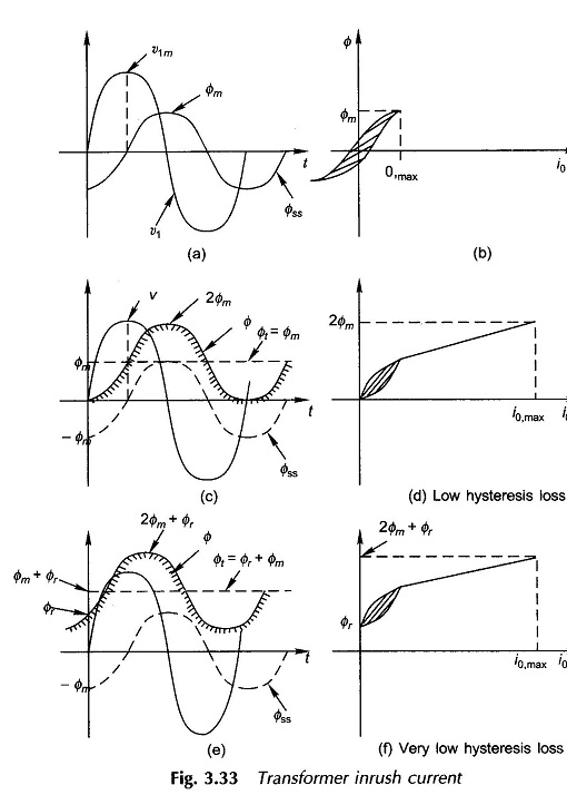
It is observed from Figs. 3.33(c) and (e) that the offset flux is unidirectional so that the transient flux and exciting current are unidirectional in the initial stage of the transient. A typical oscillogram of the Transformer Inrush Current is shown in Fig. 3.34.