What is Multistage Amplifier? – Types, Block Diagram and Analysis
Amplifiers that produce voltage, current, and/or power gain through the use of two or more stages are called multistage amplifiers. It may be emphasized here that a practical amplifier is always a multistage amplifier that may provide a higher voltage or current gain or both.
In a multistage amplifier, the output of first stage is combined to the next stage through a coupling device. The process is known as cascading. The coupling device is used to (i) transfer the ac output of one stage to the input of the next stage and (ii) block the dc to pass from one stage to the next stage i.e. to isolate the dc conditions.
For an ideal coupling network the following requirements should be fulfilled.
- It should not disturb the dc bias conditions of the amplifiers being coupled. This means direct currents should not pass through the coupling network.
- The coupling network should transfer ac signal waveform from one amplifier to the next amplifier without any distortion.
- Although some voltage loss of signal cannot be avoided in the coupling network but this loss should be minimum, just negligible.
- The coupling network should offer equal impedance to the various frequencies of signal wave. In other words the network impedance should not be frequency dependent.
Unfortunately, there is no coupling network which fulfills all the above demands. The four basic methods of coupling are R-C coupling, Transformer coupling, Impedance coupling, and Direct coupling.
The coupling network not only couples two stages; it also forms a part of the load impedance of the preceding stage. Thus, the performance of the amplifier will also depend upon the type of coupling network used. Amplifier is usually named after the type of coupling employed such as R-C coupled amplifier, transformer coupled amplifier, impedance coupled amplifier, and direct coupled amplifier.
In R-C coupling, a resistor and a capacitor are used as a coupling device. The capacitor connects the output of one stage to the input of next stage to pass ac signal and to block the dc bias voltages. The amplifier using R-C coupling is called the R-C coupled amplifier.
In transformer coupling, transformer is used as the coupling device. The amplifier using transformer coupling is called the transformer coupled amplifier. In this case there is no need of using a coupling capacitor because the secondary of the coupling transformer conveys the ac component directly to the base of the second stage. Moreover, the secondary winding also provides a base return path and so base resistance is not required.
In direct coupling or dc coupling, the individual amplifier stage bias conditions are so designed that the two stages may be directly connected without the necessity of dc isolation. This coupling is used where it is desirable to connect the load directly in series with the output terminal of the active circuit element such as in case of headphones, loudspeakers etc. The amplifier using direct coupling is called the direct coupled amplifier.
R-C coupling is the most commonly used coupling between the two stages of a cascaded or multistage amplifier because it is cheaper in cost and very compact circuit and provides excellent frequency response.
The most suitable transistor configuration for cascading is CE configuration because the voltage gain of common emitter amplifier is greater than unity while CC configuration has voltage gain less than unity and the voltage gain of CB configuration using cascading is also less than unity.
However, for input stage CC or CB configuration may be required for proper impedance matching at the cost of voltage or current gain. It is noteworthy point that for input stage, the consideration is not the maximum voltage gain but the impedance matching of the source with the input impedance of the input stage. Some driving sources may need input circuit to be an almost open circuit while others need an almost short circuit. In certain cases choice of configuration for the input stage is the minimization of noise and maximization of signal/noise power ratio.
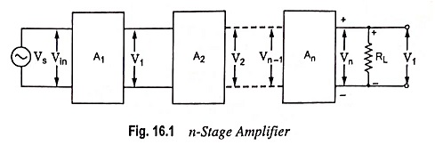
Block Diagram of a Multistage Amplifier:
A multistage amplifier can be represented by a block diagram, as shown in Fig. 16.1. It is to be noted that the output of the first stage makes the input for the second stage, the output of second stage makes the input for third stage and so on. The signal voltage Vs is applied to the input of the first stage and the final output Vout is available at the output terminals of the last stage.
Input to the first stage,
![]()
Output of first stage or input to the second stage
![]()
- where Av1 is the voltage gain of first stage
Output of second stage or input to the third stage
![]()
- where Av2 is the voltage gain of the second stage
Similarly the output of nth stage (or final output),
![]()
- where Avn is the voltage gain of the last stage
Overall voltage gain of the amplifier is given as
![]()
(visualizing the multistage amplifier as a single amplifier with input voltage Vs and output voltage Vout)
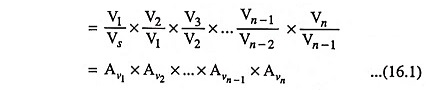
i.e. the gain of a multistage amplifier is equal to the product of gains of individual stages. It is worthwhile to mention here that in practice total gain A is less than Av1 x Av2 x … x Av n-1 x Avn due to the loading effects of the following stages.
When the gains are expressed in dB, the overall gain of a multistage amplifier is given as the sum of gains of individual stages in decibels (dB).
Taking logarithm (to the base 10) of Eq. (16.1) and then multiplying each term by 20 we have
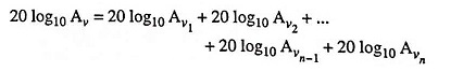
In the above equation, the term to the left is the overall gain of the multistage amplifier expressed in decibels. The terms on the right denote the gains of the individual stages expressed in decibels. Thus
![]()