Differential Amplifier With Three OP Amp:
Differential Amplifier With Three OP Amp, depicted in Fig. 34.47 consists of two stages—one formed by op-amps A1 and A2 and second by op-amp A3. Hence for determination of overall voltage gain of the circuit shown in Fig. 34.47, it becomes imperative to determine the voltage gain of each stage.
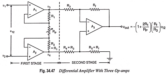
The first stage may be viewed as two differential amplifiers, as depicted in Fig. 34.48.
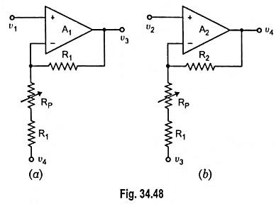
The output voltages of the two differential amplifiers shown in Fig. 34.48 are determined by using superposition theorem.
For circuit depicted in Fig. 34.48 (a)

and for circuit depicted in Fig. 34.48 (b)
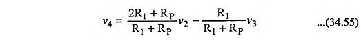
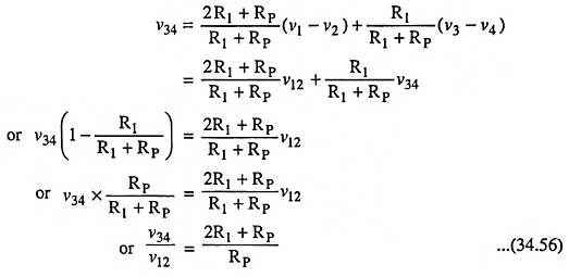
The output voltage of the first stage may be given as
![]()
Substituting the values of v3 and v4 respectively from Eqs. (34.54) and (34.55) in above equation, we have
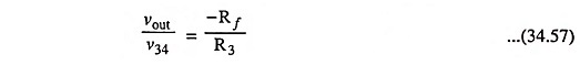
The gain of the second stage may be determined using Eq. (34.42) and is given by
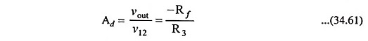
The overall voltage gain is given by
![]()
Substituting the values of v34/v12 and vout/v34 respectively from Eqs. (34.56) and (34.57) in above equation, we have
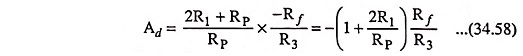
Thus the obtainable gain can be changed by adjusting the potentiometer (RP) but it should never be set at zero or infinity. In case RP is made zero, the obtainable voltage gain Ad will become indeterminant, whereas in case RP is made infinity (open-circuit), the first stage will act as a voltage follower.
Input Resistance: The input resistance of the differential amplifier with three Op amp circuit depicted in Fig. 34.47 is the same as the input resistance of the first stage (the resistance determined at input v1 and v2) looking into the circuit with other terminal grounded.
In Fig. 34.48 (a), for example, when v4 is reduced to zero (i.e. when v2 is grounded), the circuit is a noninverting amplifier and the input impedance is given as
Similarly, the input resistance determined at input v2 will be the same as determined above [Eq. (34.59)].
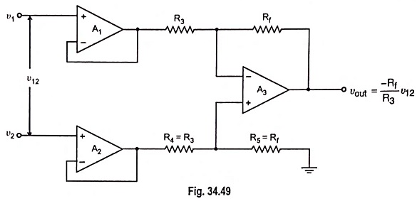
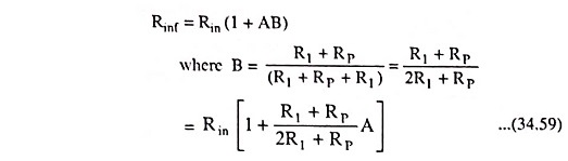
If the differential amplifier circuit depicted in Fig. 34.47 is slightly modified by replacing the first stage by voltage followers, as depicted in Fig. 34.49, we have a circuit that has the main advantage of possessing highest input resistance of three amplifiers and this resistance is given by
![]()
where Rin is the input resistance of the op-amp and A is the open-voltage gain of the op-amp.
However, the voltage gain of the circuit given in Fig. 34.49 is the same as the voltage gain of the differential amplifier with one op-amp i.e.