Class AB Power Amplifier Working Principle:
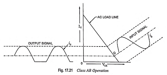
In class AB power amplifier, the biasing circuit is so adjusted that the operating point Q lies near the cutoff voltage. During a small portion of negative half cycle and for complete positive half cycle of the signal, the input circuit remains forward biased and hence collector current flows. But during a small portion (less than half cycle) of the negative cycle, the input circuit is reverse biased and, therefore, no collector current flows during this period. Class AB operation needs a push-pull connection to achieve a full output cycle.