Transformer Coupled Class A Amplifier:
Class A Circuit – Instead of capacitor coupling, a Transformer Coupled Class A Amplifier may be used to ac couple amplifier stages while providing dc isolation between stages. The resistance of the transformer windings is normally very small, so that there is no effect on the transistor bias conditions.
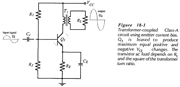
Figure 18-1 shows a load resistance (RL) transformer-coupled to a transistor collector. The low resistance of the transformer primary winding allows any desired level of (dc) collector current to flow, while the transformer core couples all variations in IC to RL via the secondary winding. This circuit is an emitter current bias circuit with voltage divider resistors R1 and R2 determining the transistor base voltage (VB), and resistor RE setting the emitter current level.
The circuit in Fig. 18-1 is referred to as a class-A amplifier, which is defined as one that has the Q-point (bias point) approximately at the center of the ac load line. This enables the circuit to produce maximum equal positive and negative changes in VCE.
DC and AC Loads:
The total dc load for transistor Q1 in the circuit in Fig. 18-1 is the sum of the emitter resistor (RE) and the transformer primary winding resistance (Rpy).
![]()
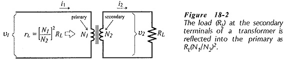
Consider the transformer illustrated in Fig. 18-2. N1 is the number of turns on the primary winding, and N2 is the number of secondary turns. The primary ac voltage and current are v1 and i1 and the secondary quantities are v2 and i2. The The (secondary) load resistance can be calculated as,
![]()
The ac load resistance measured at the transformer primary terminals (rL) is calculated as,
From basic transformer theory,
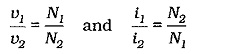
These equations give,
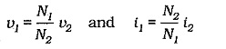
Substituting for v1 and i1 in the equation for rL,
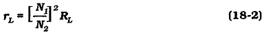
The load resistance calculated in this way is termed the reflected load, or the referred load; meaning that RL is reflected or referred from the transformer secondary to the primary as rL. The total ac load at the transistor collector is the sum of the referred load and the transformer primary winding resistance,
![]()
Collector Voltage Swing:
The ac load line is shown in Fig. 18-5 to show the effect of an input signal. When the input causes IB to increase from 50 μA (at IBQ) to 90 μA, the current and voltage become IC ≈ 9 mA and VCE ≈ 1.6V, (point C on the ac load line). The changes are: ΔIC = +4 mA, and ΔVCE = -6.4 V. When the input causes IB to decrease (from IBQ) to 10 μA, IC changes from 5 mA to 1 mA, and the VCE changes from 8 V to 14.4 V, (point D). The current and voltages changes are now: ΔIC = -4 mA and ΔVCE = +6.4 V.
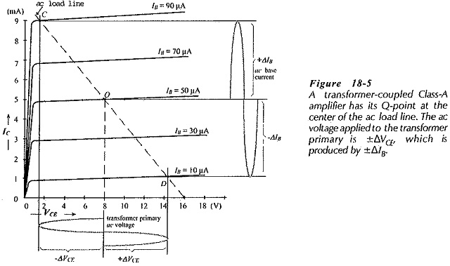
It is seen that an IB change of ±40 μA produces a ±4 mA IC change and a ±6.4 V change in VCE. The VCE variation appears at the primary winding of transformer T1, and the IC variation flows in the primary winding.
Note that, although VCC = 13 V, the transistor VCE can actually go to 16 V. This is due to the inductive effect of the transformer primary winding. The transistor used in this type of circuit should have a minimum breakdown voltage approximately equal to 2 VCC.
Efficiency of a Class A Amplifier:
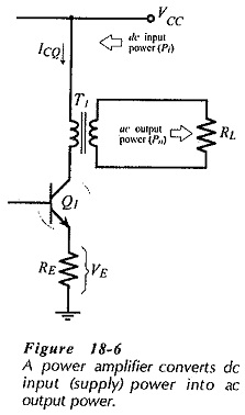
Power is delivered to an amplifier from the dc power supply. The amplifier converts the do power into ac power delivered in the load, (see Fig. 18-6). Some of the input power is dissipated in the transistor or in other components. This is wasted power. The efficiency (η) of a power amplifier is a measure of how good the amplifier is at converting the dc input (supply) power (Pi) into ac output power (Po) dissipated in the load.
The do supply power is,
![]()
the case of a class A amplifier, Iave = ICQ.
![]()
Refer again to the class A circuit in Fig. 18-6, and assume that VE ≪ VCC. In this case, VCEQ is approximately equal to VCC, and the peak voltage developed across the transformer primary approaches ±VCC if the transistor is driven to cutoff and saturation. Also, the peak current developed in the transformer windings approaches ±ICQ. Thus, the maximum ac power delivered to the transformer primary can be calculated as,
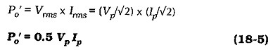
Using the highest possible current and voltage levels, and assuming that the transformer is 100% efficient,
![]()
The maximum theoretical efficiency for a Class-A transformer-coupled power amplifier can now be determined as,
![]()
In a practical Class-A transformer-coupled power amplifier circuit, 50% efficiency is never approached. Any practical calculation of power amplifier efficiency must take the output transformer efficiency (ηt) into account.
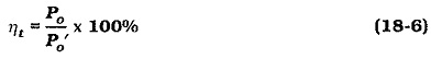
A typical transformer efficiency might be 80%. There is also power dissipation in the transistor emitter resistor and in the bias circuit. The practical maximum efficiency for a Class-A power amplifier is usually around 25%. This means, for example, that 4 W of dc supply power must be provided to deliver 1 W of ac output power to the load.