Class B Power Amplifier – Operation and Efficiency derivation:
In Class B Power Amplifier operation, the transistor is so biased that zero signal collector current is zero. Hence class B operation does not need any biasing system. The operating point is set at cutoff, as illustrated in Fig. 17.18. It remains forward biased for only half cycle of the input signal i.e., its conduction angle is 180°.
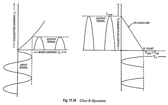
As illustrated in Fig. 17.18, during the positive half cycle of the input ac signal, the circuit is forward biased and, therefore, collector current flows. On the other hand, during negative half cycle of the input ac signal, the circuit is reverse biased and no collector current flows.
Power and Efficiency Calculations:
Input dc power, Pin (dc) = VCC Idc where Idc is the average or direct current taken from the collector supply.
If Ic max is the maximum or peak value of collector or output current, then
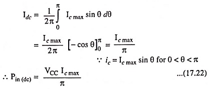
RMS value of collector current,
![]()
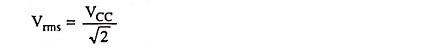
RMS value of output voltage,
Hence output power during half cycle,
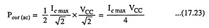
In above equation factor 1/2 is used because power is developed during one half cycle only.
DC power loss in load,
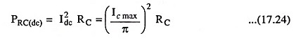
DC power loss in collector region or transistor
![]()
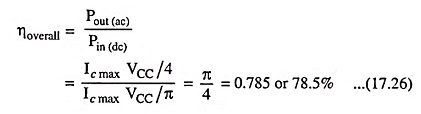
Overall efficiency,
Conclusions:
1. Severe distortion occurs because of total absence of negative half cycle from the output.
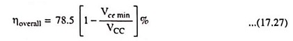
2. As average current in class B operation (Ic max)/π is less than that in class A operation, so power dissipation is less and consequently overall efficiency is high [78.5% when peak input signal makes Vce min = 0]. In general, overall efficiency is given as
3. Zero signal input represents the best condition for class B operation as collector current is zero. This is quite contrary to class A operation. In Class B Power Amplifier operation, the transistor dissipation increases with increased input signals.
4. Half sine-wave type of collector current contains very pronounced even harmonics (particularly the second one). Such impulses can be made useful either by using push-pull arrangement or by employing tuned amplifiers.