Noise in Amplifiers and its Types:
Noise in Amplifiers – Noise is any kind of unwanted signal that is not related to the input. Any electronic component produces a certain amount of noise. When these components are assembled to build a device or circuit and if a signal is supplied to it, the noise produced will get superimposed on the signal and interfere with the information contained in the signal. In case of an amplifier, noise signal will get amplified along with the input signal and will appear at the output which is undesirable. Thus, the noise places a lower limit on the amplitude of the signal that can be detected and amplified without losing the signal into the noise.
Noise may be produced by source external to the circuits in addition to internal noise phenomena in the circuits. External sources of noise are lightning, power lines in the neighborhood, ignition systems in the automobile etc., that set up electric and magnetic fields. Such fields can induce noise voltage in the electronic circuits. For reducing noise due to external sources, proper shielding of the circuit is essential. Internal noise becomes significant above about 20 MHz and makes its presence evident as a hiss or crackle when no signal or a very weak signal is available at the input to an amplifier.
Various phenomenon, that are responsible for creating Noise in Amplifiers are now considered.
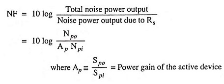
Thermal or Johnson Noise: The motion of free electrons drifting around within the material constitutes a flow of many tiny random electric currents. Such currents cause minute voltage drops, which appear across the terminals of the material. The amplitude of the generated voltage increases linearly with the rise in temperature. This is because the number of free electrons available and the random motion of the electrons are increased with the increase in temperature. This undesired, randomly varying voltage is termed thermal noise.
Thermal noise in amplifiers is generated within resistors, and when the resistors are at the input stage of an amplifier, the noise is amplified and produced as an output. Noise from other resistors is not amplified as much as that from the resistors right at the input. So only the input stage resistors need be considered in noise calculations.
Since thermal noise is an alternating quantity, its rms output level from any amplifier depends upon the bandwidth of the noise in amplifiers. The rms value of the thermal resistance noise voltage Vn over a frequency range f2 – f1 is given by the equation
![]()
where k′ is Boltzmann’s constant (1.374 x 10⁻²³ joules per Kelvin), T is absolute temperature of resistor in Kelvin, R is the resistance of the resistor in ohms and B is the circuit bandwidth (f2 – f1) in hertz.
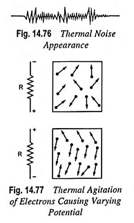
The noise voltage is shown in Fig. 14.76. The varying size and shape of the noise voltage indicates that it has components of many different frequencies. The noise is uniformly distributed throughout the entire bandwidth. The noise depends on bandwidth, temperature and the resistance.
Resistors employed near the input terminal of an amplifier should have the lowest minimum possible value. This is because the noise generated by these resistors will be amplified most and distort the input signal. The thermal noise can be reduced by lowering the amplifier operating temperature.
Shot Noise: Among the various possible sources of noise in a tube, one of the most important is the shot effect. It appears that the current in a tube under dc conditions (with no input signal) is constant at every instant. Actually, however, the current from the cathode to the anode consists of a stream of individual electrons, and it is only the time average flow which is constant. Such fluctuations in the number of electrons emitted cause the shot noise. Shot noise increases with the increase in operating current and the rms value of noise current In in a diode is given by the equation
![]()
where e is electronic charge in coulomb, Ie is the emission current in amperes and B is the bandwidth in Hz.
In addition to thermal and shot noise, the other sources that cause noise in a tube are :
- Flicker noise caused by the spontaneous emission of particles from an oxide-coated cathode, an effect particularly noticeable at low frequencies and decreasing with increasing value of frequencies.
- Partition noise caused due to fluctuations in the division of charge carriers between various electrodes.
- Induced grid noise caused due to random nature of the electron stream near the grid.
- Secondary emission noise caused due to variations in secondary emission from plate and grid.
- Gas noise caused by the random ionization of the few molecules remaining in the tube.
Noise in Transistors: In addition to thermal noise in a transistor, noise is also caused due to random motion of the charge
carriers (majority as well as minority carriers) crossing the emitter and collector junctions and due to random recombination of electrons and holes in the base. There is also a partition effect developed due to random fluctuation in the division of current between collector and the base. The amount of noise produced depends upon the quiescent conditions and the source resistance Rs. Low operating currents and use of higher than normal input resistance reduce the transistor noise.
Noise in FETs: The main source of noise in FETs are the thermal noise of the conducting channel, the shot noise caused by gate leakage current. One advantage of a FET over a BJT is that the FET usually has much lower thermal noise. This is because, unlike the bipolar transistor, there are very few charge carriers crossing a junction in the FET. This is the reason that FETs are employed near the front end of electronic equipment as the subsequent stages amplify the noise at front end along with the signal and if a FET amplifier is used at the front end, less amplified noise is obtained at the output. Thus FETs are useful for input circuits operating at low signal levels.
Noise Figure: A noise figure NF has been introduced in order to enable to specify quantitatively how noisy a circuit is. It is defined as the ratio of the noise power output of the circuit under consideration to the noise power output that would be obtained in the same frequency range if the only source of noise were the thermal noise in the internal resistance Rs of the signal source. Thus the noise figure is a quantity which compares the noise in an actual amplifier with that in an ideal (noiseless) amplifier. To arrive at this figure, the transistor noise output is measured under specified bias conditions and with a specified source resistance, temperature, and noise bandwidth.
If Spi is the signal power input to an amplifier, Npi is the noise power input due to source resistance Rs, Spo is the signal power output and Npo is the noise power output to source resistance Rs and due to other sources of noise in the device, noise figure NF is given as
Thus
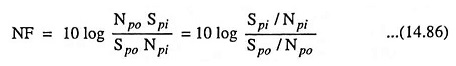
The quotient Sp/Np is called the signal-to-noise power ratio.
The noise figure NF is proportional to the input signal-to-noise power ratio divided by the output signal-to-noise power ratio.