Noise Calculation in Electronic Communication System:
The Noise Calculation in Electronic Communication System are namely,
1.Addition of Noise due to Several Sources:
Let’s assume there are two sources of thermal agitation noise generators in series: Vn1 = √4kT δf R1 and Vn2 = √4kT δf R2. The sum of two such rms voltages in series is given by the square root of the sum of their squares, so that we have
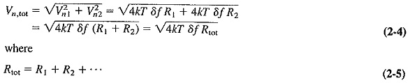
It is seen from the previous equations that in order to find the total noise voltage caused by several sources of thermal noise in series, the resistances are added and the noise voltage is calculated using this total resistance. The same procedure applies if one of those resistances is an equivalent input-noise resistance.
2.Addition of Noise due to Several Amplifiers in Cascade:
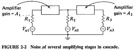
The situation that occurs in receivers is illustrated in Figure 2-2. It shows a number of amplifying stages in cascade, each having a resistance at its input and output. The first such stage is very often an RF amplifier, while the second is a mixer. The problem is to find their combined effect on the receiver noise.
It may appear logical to combine all the noise resistances at the input, calculate their noise voltage, multiply it by the gain of the first stage and add this voltage to the one generated at the input of the second stage. The process might then be continued, and the noise voltage at the output, due to all the intervening noise sources, would be found. Admittedly, there is nothing wrong with such a procedure. The result is useless because the argument assumed that it is important to find the total output noise voltage, whereas the important thing is to find the equivalent input noise voltage. It is even better to go one step further and find an equivalent resistance for such an input voltage, i.e., the equivalent noise resistance for the whole receiver. This is the resistance that will produce the same random noise at the output of the receiver as does the actual receiver, so that we have succeeded in replacing an actual receiver amplifier by an ideal noiseless one with an equivalent noise resistance Req located across its input. This greatly simplifies subsequent calculations, gives a good figure for comparison with other receivers, and permits a quick Noise Calculation in Electronic Communication System of the lowest input signal which this receiver may amplify without drowning it with noise.
Consider the two-stage amplifier of Figure 2-2. The gain of the first stage is A1, and that of the second is A2. The first stage has a total input-noise resistance R1, the second R2 and the output resistance is R3. The rms noise voltage at the output due to R3 is![]()
The same noise voltage would be present at the output if there were no R3 there. Instead R′3 was present at the input of stage 2, such that![]()
where R′3 is the resistance which if placed at the input of the second stage would produce the same noise voltage at the output as does R3. Therefore

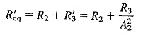
Equation (2-6) shows that when a noise resistance is “transferred” from the output of a stage to its input, it must be divided by the square of the voltage gain of the stage. Now the noise resistance actually present at the input of the second stage is R2, so that the equivalent noise resistance at the input of the second stage, due to the second stage and the output resistance, is
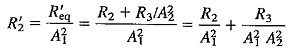
Similarly, a resistor R′2 may be placed at the input of the first stage to replace R′eq, both naturally producing the same noise voltage at the output. Using Equation (2-6) and its conclusion, we have
The noise resistance actually present at the input of the first stage is R1, so that the equivalent noise resistance of the whole cascaded amplifier, at the input-of the first stage, will be
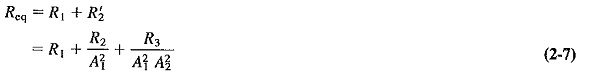
It is possible to extend Equation (2-7) by induction to apply to an n-stage cascaded amplifier, but this is not normally necessary. As Example 2-3 will show, the noise resistance located at the input of the first stage is by far the greatest contributor to the total noise, and only in broadband, i.e., low-gain amplifiers is it necessary to consider a resistor past the output of the second stage.
3.Noise in Reactive Circuits:
If a resistance is followed, by a tuned circuit which is theoretically noiseless, then the presence of the tuned circuit does not affect the noise generated by the resistance at the resonant frequency. To either side of resonance the presence of the tuned circuit affects noise in just the same way as any other voltage, so that the tuned circuit limits the bandwidth of the noise source by not passing noise outside its own bandpass. The more interesting case is a tuned circuit which is not ideal, i.e., one in which the inductance has a resistive component, which naturally generates noise.
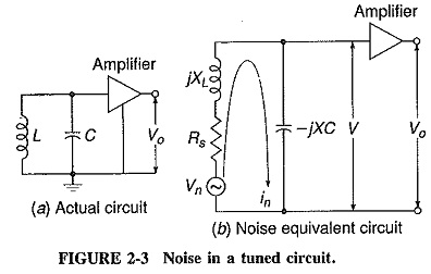
In the preceding sections dealing with Noise Calculation in Electronic Communication System, an input (noise) resistance has been used. It must be stressed here that this need not necessarily be an actual resistor. If all the resistors shown in Figure 2-2 had been tuned circuits with equivalent parallel resistances equal to R1, R2, and R3, respectively, the results obtained would have been identical. Consider Figure 2-3, which shows a parallel-tuned circuit. The series resistance of the coil, which is the noise source here, is shown as a resistor in series with a noise generator and with the coil. It is required to determine the noise voltage across the capacitor, i.e., at the input to the amplifier. This will allow us to calculate the resistance which may be said to be generating the noise.
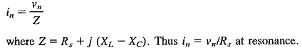
The noise current in the circuit will be
The magnitude of the voltage appearing across the capacitor, due to νn, will be
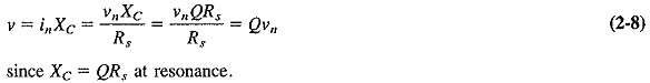
Equation (2-8) should serve as a further reminder that Q is called the magnification factor! Continuing, we have

where ν is the noise voltage across a tuned circuit due to its internal resistance, and Rp is the equivalent parallel impedance of the tuned circuit at resonance.
Equation (2-9) shows that the equivalent parallel impedance of a tuned circuit is its equivalent resistance for noise (as well as for other purposes).