What is Electronic Switch in Oscilloscope?:
The electronic switch is a device that enables two signals to be displayed simultaneously on the screen by a single gun CRT. The basic block diagram of an Electronic Switch Circuit is shown in Fig. 7.22.
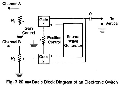
Each signal is applied to a separate gain control and gate stage. The gates stage are alternately biased to cut off by square wave signals from the square wave generator. Therefore only one gate stage is in a condition to pass its signal at any given time.
The outputs of both stages are applied directly to the oscilloscope input.
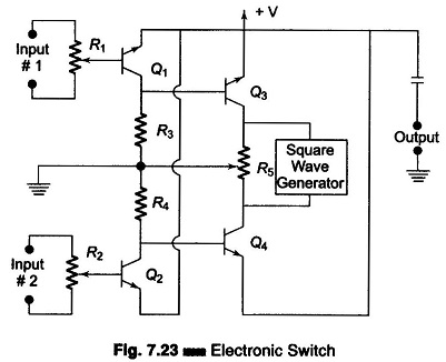
R1 and R2 are gain controls used to adjust the amplitudes of Channels A and B. In the Electronic Switch Circuit diagram of Fig. 7.23, Q1 and Q2 are the amplifiers and Q3 and Q4 the switches. Input signal 1 is applied to Q1 through gain control R1, and input signal 2 is applied to Q2 through gain control R2. The square wave generator alternately biases first Q3 and then Q4 to cut off. When Q3 is cut off, Q4 conducts and transmits signal 2 to the output terminals. When Q4 is cut off, Q3 conducts and transmits signal 1 to the output terminals.
When the square wave generator switching frequency is much higher than either signal frequency, bits of each signal are alternately presented to the oscilloscopes vertical input to reproduce the two signals on the screen.
The traces can be moved up or down by the position control R5. The traces can be overlapped for easy comparison. The heights of the individual signals can be adjusted by means of gain controls R1 and R2 The sweep signal produced by this design is very linear and can be calibrated in time per cm or inch, so that accurate time and frequency can be measured.