Waveguide Switch Design:
It is often necessary to prevent microwave power from following a particular path, or to force it to follow another path; as at lower frequencies, the component used for this purpose is called a switch. Waveguide Switch Design (or coaxial) may be mechanical (manually operated) or electromechanical (solenoid-operated). They can also be electrical, in which case the switching action is provided by a change in the electrical properties of some device. The electrical type of switch will be the only one described here. It is conveniently categorized by the device used, which may be a gas tube, a semiconductor diode, or a piece of ferrite material. A very common application of such Waveguide Switch Design will be described, namely, the duplexer (as used in radar).
Gas Tube Switches:
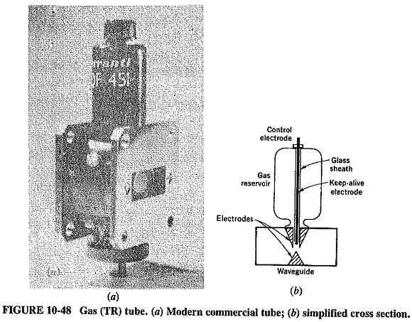
A typical gas-tube switch, or TR (transmit-receive) cell, is shown in Figure 10-48. It consists basically of a piece of waveguide filled with a gas mixture, such as hydrogen, argon, water vapor and ammonia, kept at a low pressure of a few millimeters of mercury to help ionization and terminated at either end by resonant windows. These are often made of glass, which is virtually transparent to microwaves but which prevents any gas from escaping. In the center of the waveguide there is a. pair of electrodes, looking faintly like a stalactite and a stalagmite and having the function of helping the ionization of the gas by virtue of being close together, thus increasing the electric field at this point.
At low applied powers, such as those coming from the antenna of a microwave receiver, the gas tube behaves much like an ordinary piece of waveguide, and the signal passes through it with an insertion loss that is typically about 0.5 dB. When a high-power pulse arrives, however, the gas in the tube ionizes and becomes an almost perfect conductor. This has the effect of placing a short circuit across the waveguide leading to the gas tube. Thus the power that passes through it does so with an attenuation that can exceed 60 dB in practice. The tube acts as a self-triggered switch, since no bias or synchronizing voltage need be applied to change it from an open circuit to a short circuit.
A Waveguide Switch Design such as this must act very rapidly. From the gas tube’s point of view, this means that quick ionization and deionization are required. Ionization must be quick to ensure that the initial spike of power cannot pass through the TR cell and possibly damage any equipment on the other side of it. Quick deionization is needed to ensure that the receiver connected to the other end of the tube does not remain disconnected from the antenna for too long. The first requirement is helped by the inclusion of a keep-alive electrode, to which a dc voltage is applied to ensure that ionization occurs as soon as any significant microwave power is applied. The second requirement may be helped by a suitable choice of gas. Finally, present-day gas tubes are capable of switching very high powers indeed (in excess of 10 MW pulsed if required).
Semiconductor Diode Switches:
A number of semiconductor diodes may be used as switches, by virtue of the fact that their resistance may be changed quickly, by a change in bias, from forward to reverse and back again. Point-contact diodes have been used for this purpose, but their power-handling ability is very low, and the most popular switching diode is the PIN diode. Not only does its resistance change significantly with the applied bias, but also it is capable of handling appreciable amounts of power. Several diodes may be used in parallel to increase the power-handling ability even further.
A PIN (or any other) diode switch may be mounted as shown in Figure 10-45, except that there is now no wall on the right-hand side of the Waveguide Switch Design. Instead, the guide continues and is eventually connected to some device such as a receiver. Such a diode switch may be passive or active. The passive type is simpler because it just has the diode connected across the waveguide. It then relies on the incidence of high microwave power to cause the diode to conduct and therefore to become a short circuit which reflects the power so as to prevent its further passage down the waveguide. An active diode switch has a reverse bias applied to it in the absence of incident power. Simultaneously with the application of high power, the bias is changed to forward, and the diode once again short-circuits that portion of waveguide. Back bias is then applied at the same time as the pulse ends. The advantage of this somewhat more complex arrangement is a reduction in the forward and reverse loss (so that they are both comparable to those of the TR tube), and a very significant increase in the maximum power handled.
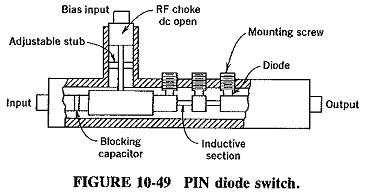
A practical PIN diode switch is shown in Figure 10-49 and is seen to consist of a number of diodes in parallel. Such an arrangement allows peak powers of several hundred kilowatts to be switched. The advantages of the PIN diode switch, compared with the TR tube, are its greater life and reliability, as well as smaller size and the removal of the initial spike of power coinciding with the beginning of the pulse. It handles less power, however, and is slower in high-power applications, although in low-power switching and pulse modulation PIN diodes are capable of switching times under 10 ns.
Ferrite switches:
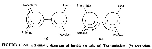
The properties of ferrites, as described in Section 10-5.2, make them suitable also for switching operations. A typical Waveguide Switch Design is the pair of Y circulators shown in Figure 10-50, in which the direction of the magnetic field can be reversed for the second circulator. This is accomplished by providing bias changes in the form of current reversals through the solenoid which is used to generate the magnetic field for this circulator. It can be seen, from the previous discussion of circulators and the signal paths shown in Figure 10-50, that in the “transmit” condition very little power from the transmitter will enter the second circulator, and most of the power that does will be dissipated in the matched load. In the “receive” state, the magnetic bias will be (externally) reversed for the second circulator, so that the signal from the antenna will be coupled to the receiver. The action of the first circulator will prevent this signal from entering the transmitter. Ferrite switches are capable of switching hundreds of kilowatts peak, with low losses, long life and high reliability, but they are not yet as fast as gas tubes.
Duplexers:
A duplexer is a circuit designed to allow the use of the same antenna for both transmission and reception, with minimal interference between the transmitter and the receiver. From this description it follows that an ordinary circulator is a duplexer, but the emphasis here is on a circuit using switching for pulsed (not CW) transmission.
The branch-type duplexer shown in Figure 10-51 is a type often used in radar. It has two switches, the TR and the ATR (anti-TR), arranged in such a manner that the receiver and the transmitter are alternately connected to the antenna, without ever being connected to each other. The operation is as follows.
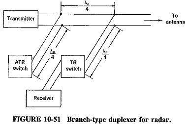
When the transmitter produces an RF impulse, both switches become short-circuited either because of the presence of the pulse, as in TR cells, or because of an external synchronized bias change. The ATR switch reflects an open circuit across the main waveguide, through the quarter-wave section connected to it, and so does the TR switch, for the same reason. Therefore, neither of them affects the transmission, but the short-circuiting of the TR switch prevents RF power from entering the receiver or at least reduces any such power down to a tolerable level. At the termination of the transmitted pulse, both switches open-circuit by a reversal of the initial short-circuiting process. The ATR switch now throws a short circuit across the waveguide leading to the transmitter. If this were not done, a significant loss of the received signal would be incurred. At the input to the guide joining the TR branch to the main waveguide, this short circuit has now become an open circuit and hence has no effect. Meanwhile, the guide leading through the TR switch is now continuous and correctly matched. The signal from the antenna can thus go directly to the receiver.
The branch-type duplexer is a narrowband device, because it relies on the length of the guides connecting the Waveguide Switch Design. Single-frequency operation is very often sufficient, so that the branch-type duplexer is very common.