Parallel Plane Waveguide:
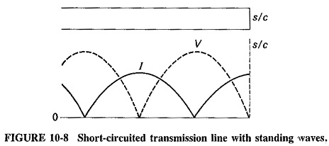
Parallel Plane Waveguide – As we know already in connection with transmission lines, that reflections and standing waves are produced if a line is terminated in a short circuit, and that there is a voltage zero and a current maximum at this termination. This is illustrated again in Figure 10-8, because it applies directly to the situation described in electromagnetic waves at a conducting boundary.
A rectangular waveguide has two pairs of walls, and we shall be considering their addition one pair at a time. It is now necessary to investigate whether the second wall in a pair may be added at any distance from the first, or whether there are any preferred positions and, if so, how to determine them. Transmission-line equivalents will continue to be used, because they definitely help to explain the situation.
Addition of a second wall:
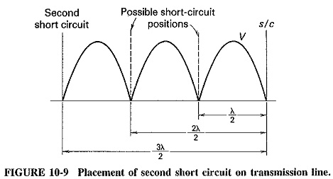
If a second short circuit is added to Figure 10-8, care must be taken to ensure that it does not disturb the existing wave pattern (the feeding source must somehow be located between the two short-circuited ends). Three suitable positions for the second short circuit are indicated in Figure 10-9. It is seen that each of them is at a point of zero voltage on the line, and each is located at a distance from the first short circuit that is a multiple of half-wavelengths.
The presence of a reflecting wall does to electromagnetic waves what a short circuit did to waves on a transmission line. A pattern is set up and will be destroyed unless the second wall is placed in a coned position. The situation is illustrated in Figure 10-10, which shows the second wall, placed three half-wavelengths away from the first wall, and the resulting wave pattern between the two walls.
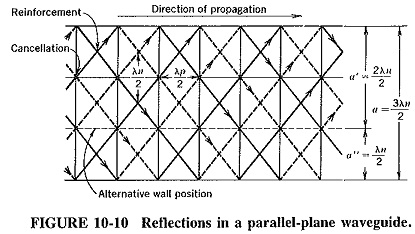
A major difference from the behavior of transmission lines is that in Parallel Plane Waveguide the wavelength normal to the walls is not the same as in free space, and thus a = 3λn/2 here, as indicated. Another important difference is that instead of saying that “the second wall is placed at a distance that is a multiple of half-wavelengths,” we should say that “the signal arranges itself so that the distance between the walls becomes an integral number of half-wavelengths, if this is possible.” The arrangement is accomplished by a change in the angle of incidence, which is possible so long as this angle is not required to be “more perpendicular than 90°.” Before we begin a mathematical investigation, it is important to point out that the second wall might have been placed (as indicated) so that a′ = 2λn/2, or a″ = λn/2, without upsetting the pattern created by the first wall.
Cutoff wavelength:
If a second wall is added to the first at a distance a from it, then it must be placed at a point where the electric intensity due to the first wall is zero, i.e., at an integral number of half-wavelengths away. Putting this mathematically, we have
![]()
where
a = distance between walls
λn = wavelength in a direction normal to both walls
m = number of half-wavelengths of electric intensity to be established between the walls (an integer)
Substituting for λn from Equation (10-4) gives
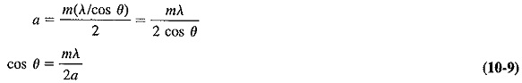
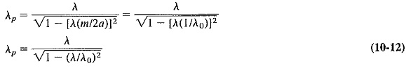
The previous statements are now seen in their proper perspective: Equation (10-9) shows that for a given wall separation, the angle of incidence is determined by the free-space wavelength of the signal, the integer m and the distance between the walls. It is now possible to use Equation (10-9) to eliminate λn from Equation (10-3), giving a more useful expression for λp, the wavelength of the traveling wave which propagates down the waveguide. We then have
![]()
From Equation (10-10), it is easy to see that as the free-space wavelength is increased, there comes a point beyond which the wave can no longer propagate in a waveguide with fixed a and m. The free-space wavelength at which this takes place is called the cutoff wavelength and is defined as the smallest free-space wavelength that is just unable to propagate in the waveguide under given conditions. This implies that any larger free-space wavelength certainly cannot propagate, but that all smaller ones can. From Equation (10-10), the cutoff wavelength is that value of λ for which λp becomes infinite, under which circumstance the denominator of Equation (10-10) becomes zero, giving
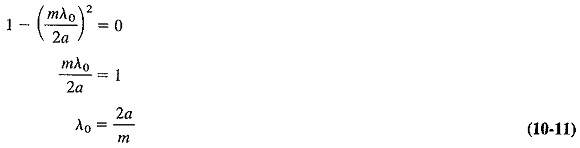
where
λ0 = cutoff wavelength.
The largest value of cutoff wavelength is 2a, when m = 1. This means that the longest free-space wavelength that a signal may have and still be capable of propagating in a Parallel Plane Waveguide, is just less than twice the wall separation. When m is made unity, the signal is said to be propagated in the dominant mode, which is the method of propagation that yields the longest cutoff wavelength of the guide.
It follows from Equation (1040) that the wavelength of a signal propagating in a waveguide is always greater than its free-space wavelength. Furthermore, when a Parallel Plane Waveguide fails to propagate a signal, it is because its free-space wavelength is too great. If this signal must be propagated, a mode of propagation with a larger cutoff wavelength should be used, that is, m should be made smaller. If m is already equal to 1 and the signal still cannot propagate, the distance between the walls must be increased.
Finally, Equation (10-11) may be substituted into Equation (10-10) to give the very important universal equation for the guide wavelength, which does not depend on either waveguide geometry or the actual mode (value of m) used. The guide wavelength is obtained in terms of the free-space wavelength of the signal, and the cutoff wavelength of the Parallel Plane Waveguide, as follows:
Cutoff frequency:
For those who are more familiar with the term cutoff frequency instead of cutoff wavelength, the following information and examples will show how to use these terms to calculate the lowest cutoff frequency.
The lower cutoff frequency for a mode may be calculated by Equation (10-13).

where
fc = lower cutoff frequency in hertz
a and b = waveguide measurements in meters
m and n = integers indicating the mode